Introduction
Internal bore air pressure is one of the most consequential variables in plastic tubing extrusion — and historically, one of the last to be automated. While temperature zones and haul-off speeds were brought under PLC control years ago on most modern lines, pressure regulation often stayed manual: an operator turning a knob, checking tubing OD, adjusting again.
That works until it doesn't. Shift changes, material viscosity swings, cut cycles, and bump tubing transitions all expose the limits of hand-adjusted pressure control.
For medical catheter manufacturers working in tolerances measured in ten-thousandths of an inch, or automotive tubing producers bound by documented process control requirements, "close enough" isn't a viable quality standard.
What follows is a practical guide for process engineers, production managers, and technical staff at plastic tubing manufacturers. It covers what the upgrade from manual to PLC-controlled pressure regulation actually involves, why ultra-low free-extrusion pressures demand specialized equipment, and what separates a real quality gain from added complexity.
Key Takeaways
- Manual pressure regulation is reactive and operator-dependent — PLC control removes that dependency entirely
- A motorized potentiometer bridges PLC analog output to the regulator's adjustment mechanism
- Free extrusion bore pressures often fall below 1 inch of water column — standard industrial regulators cannot control at this range
- Hysteresis-free regulator performance is non-negotiable for PLC integration to produce meaningful OD improvements
- Automated pressure control makes bump and taper production feasible — manual transitions simply cannot keep pace
Manual vs. PLC-Controlled Pressure Regulation: Understanding the Difference
What Manual Control Actually Looks Like
In manual pressure regulation, an operator physically turns a knob or valve to set the internal air pressure inside the tubing bore. They watch the OD gauge, assess whether the tube looks right, and adjust. It's reactive — there's no closed loop, no automatic correction, no memory of what worked last time. The quality of pressure control at any moment depends entirely on who is running the line and how much attention they're paying.
This matters more than it sounds. In free extrusion of plastic tubing, internal air pressure is what supports the bore during draw-down from the die through the cooling trough. According to On Line Controls, free extrusion uses internal air pressure rather than external vacuum to control inner diameter and wall thickness — and the pressures involved can be below 1 inch of water column (0.036 psi). At those levels, a small hand-adjustment can create significant OD variation before the operator notices anything on the gauge.
What PLC Control Changes
PLC-controlled pressure regulation removes the human adjustment loop. The PLC receives a target pressure or OD setpoint, sends an analog signal to a motorized actuator, which physically adjusts the regulator's output — continuously, automatically, without operator input.
This is architecturally different from manual control in two ways:
- Setpoint precision: The PLC commands a specific value within the operating range, not an approximate hand position on a knob
- Response speed: When line conditions change — a cut cycle, a speed adjustment, a bump tubing transition — the PLC responds in milliseconds, not seconds
Bore pressure differs fundamentally from other PLC-controlled parameters. Temperature zones and screw speed coordination are standard PLC territory — and those systems operate at pressures that general industrial components handle without issue. Bore air pressure in free extrusion is orders of magnitude lower, which means standard pneumatic regulators, even PLC-driven ones, lack the resolution this application requires. Components rated for ultra-low pressure — below 1 inch of water column — are the appropriate fit here.
Why Plastic Tubing Extrusion Lines Need PLC-Controlled Pressure Regulation
The Tolerance Problem
Medical tubing processors routinely work in tolerance ranges measured in ten-thousandths of an inch. Graham Engineering cites microbore tolerance targets of ±0.0005 inches or less. At those windows, bore pressure variation that an operator might not detect for several seconds translates directly into out-of-spec tubing.
Research published in PMC confirms the mechanism: increased internal air pressure generates radial forces inside the tube that reduce wall thickness. No manual process can maintain that consistency reliably across a full production shift.
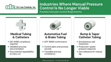
Industries Where Manual Control Is No Longer Viable
Three sectors make the case most clearly:
- Medical tubing and catheters — ISO 13485 requires controlled production conditions and process validation when output cannot be verified by later measurement. When bore pressure is a validated process variable, it needs to be documented and repeatable
- Automotive fuel and brake tubing — IATF 16949 requires control plans at the component and material level; manual pressure adjustment doesn't generate the documented process records these systems require
- Bump and taper catheter tubing — wall thickness transitions must occur simultaneously with puller speed changes, at production speeds where manual response is physically impossible
Where Operator Dependency Creates Risk
There's a knowledge-transfer problem that compounds the quality issue. When an experienced line operator who "knows" the right pressure setting for each die and product combination retires or moves on, that institutional knowledge leaves with them. It isn't written down anywhere. The next operator starts from scratch.
PLC-controlled pressure with recipe-based setpoints solves this directly. The correct starting pressure for each product and die combination is stored digitally. Changeover becomes repeatable regardless of who is running the line. That matters more each year: according to the National Association of Manufacturers, the U.S. could face 1.9 million unfilled manufacturing positions by 2033.
The Cut Cycle and Spooling Problem
The knowledge-transfer problem is a human risk. Cut cycles and spooling transitions are a mechanical one — and manual control fails there too. When a cut is made, flow demand inside the tube changes suddenly. A well-designed pressure regulator compensates instantly. An operator cannot.
OLC's MicroAir IV, for example, responds to a 50% full-scale step change in less than 0.1 second (typically 20 milliseconds). That's the performance standard required to maintain consistent bore pressure through production events no human can match in real time.
How the Upgrade from Manual to PLC Pressure Control Works
The core of the upgrade is straightforward: replace the hand-turned adjustment mechanism on the pressure regulator with a motorized actuator that accepts an analog signal from the PLC. The regulator body may stay in place; what changes is how its setpoint is commanded.
Step 1: Audit the Existing Pressure Regulation Setup
Before ordering any hardware, evaluate:
- Current regulator type — is it purpose-built for ultra-low pressure, or a standard industrial regulator someone installed years ago?
- Operating pressure range — if pressures are below 1 inch of water column, standard industrial regulators cannot be used regardless of what actuator is attached
- Motorized actuation compatibility — can the existing regulator accept a motorized actuator, or does the regulator itself need replacement?
This audit step is where most upgrade projects either succeed or fail before they start. Teams that skip it and wire in a motorized actuator to an incompatible regulator typically find pressure variation increases rather than decreases.
Step 2: Select and Install a Compatible Motorized Actuator
The motorized potentiometer is the physical interface between the PLC's digital world and the analog regulator. The PLC sends a setpoint command (0–10V or 4–20mA), the motorized potentiometer translates that into a mechanical rotation of the regulator's adjustment mechanism, and pressure changes accordingly.
OLC's motorized potentiometer line is specifically designed for this application, combining a precision linear potentiometer, slip clutch, geartrain, and motor in a single panel-mount assembly. The slip clutch protects the potentiometer's end stops and allows manual override when the motor is off. These units pair directly with OLC's MicroAir regulator line, which was purpose-built for the ultra-low pressure ranges free extrusion requires.
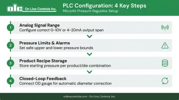
Step 3: Configure PLC Logic and Set Process Recipes
PLC configuration determines how much time and material the upgrade actually saves across every production run. At minimum, the PLC must:
- Send the correct analog signal range to the motorized potentiometer across the full operating span
- Set safe upper and lower pressure limits with appropriate alarms
- Store product recipes with the correct starting pressure for each product/die combination
- Accept closed-loop feedback from downstream OD measurement for automatic correction
Recipe-based setpoints are the practical payoff for most production operations. When a line changeover happens, the operator recalls the stored recipe rather than starting from scratch, eliminating the trial-and-error startup that consumes time and material.
For closed-loop control, connecting a laser micrometer or OD gauge output to the PLC lets pressure respond to actual measured tubing dimensions rather than a fixed setpoint. This is particularly valuable on medical or catheter lines where dimensional tolerances are tight and manual corrections introduce risk.
Key Factors That Affect Upgrade Success
Pressure Range Compatibility
This is the single most common oversight. Standard industrial pneumatic components operate at pressures measured in PSI. Free extrusion bore pressures operate at fractions of a PSI — the MicroAir product line handles ranges as low as 0–0.25 inches of water, with most medical tubing applications falling between 0–15 and 0–30 inches of water (below 1 psi).
A regulator designed for 0–100 PSI control cannot deliver stable, repeatable performance at 0.5 inches of water. The physics don't scale — spring tensions, seal dynamics, and response characteristics are all wrong for sub-PSI operation.
Hysteresis and Response
Beswick Engineering defines regulator hysteresis as the difference in output pressure at a specified flow when the setpoint is approached from above versus below — caused by friction in springs and seals. In ultra-low pressure systems, even small hysteresis creates visible OD variation.
OLC's MicroAir achieves hysteresis-free operation through two design features working together:
- A force balance system where the relief valve stem floats vertically on a low-tension spring, making friction negligible
- A viscostatic damping chamber below the pressure relief valve that prevents oscillation without introducing lag
Off-the-shelf pneumatic components — even quality ones — are built for PSI-range dynamics. At inches-of-water pressures, their spring tensions and seal friction produce the exact instability that causes tubing OD to drift.
PLC Signal Resolution
Major PLC manufacturers including Siemens, Beckhoff, and Rockwell publish 16-bit analog output modules as standard offerings (with Rockwell's ControlLogix family ranging 13–16 bit depending on module selection). Higher resolution translates directly to finer incremental pressure commands — on a 0–30 inWC span, 16-bit resolution yields steps of roughly 0.0005 inches of water, which matters when you're chasing ±0.001" OD tolerances.
Open-Loop vs. Closed-Loop Control
Two architectures are available:
| Approach | How It Works | Best For |
|---|---|---|
| Open-loop (recipe-based) | PLC sends fixed setpoint from stored recipe | Stable products with consistent materials |
| Closed-loop | PLC adjusts pressure based on real-time OD measurement feedback | Tight-tolerance medical tubing, variable material runs |
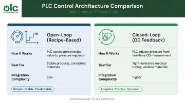
Closed-loop control requires a downstream laser micrometer or OD gauge with analog output connected to the PLC. It delivers the highest dimensional consistency but requires more integration work to configure correctly.
Common Mistakes and Misconceptions About PLC Pressure Control Upgrades
Three failure patterns appear repeatedly on PLC pressure control upgrade projects. Recognizing them before you start saves time, money, and the frustration of a system that underperforms its manual predecessor.
- Wrong regulator class: Standard process regulators and motorized valves are built for PSI-range systems. Retrofitting them to handle sub-1-PSI bore air typically produces worse results than the manual setup they replaced — the components aren't stable at those pressures. The regulator must be purpose-built for ultra-low pressure tubing extrusion.
- Hardware-only thinking: Teams wire in the motorized actuator, confirm it moves on a PLC signal, and call the project done. Without recipe management, alarm limits, and proper PLC logic, the upgrade only reduces manual intervention during steady-state runs. It won't capture the full benefit at changeover, startup, or bump/taper transitions.
- Over-relying on the PLC: The PLC and actuator control the setpoint. Pressure delivery quality depends entirely on the regulator itself. A regulator with significant hysteresis, pressure droop, or instability at the operating range introduces variation the PLC cannot correct, regardless of how well the control logic is written.
Frequently Asked Questions
What is the difference between manual and PLC-controlled pressure regulation on an extrusion line?
Manual control requires an operator to physically adjust the regulator setpoint by hand, with no automatic correction. PLC control uses a motorized actuator to adjust the setpoint automatically based on programmed recipes or closed-loop measurement feedback, eliminating operator dependency and maintaining consistent bore pressure across shifts and product changeovers.
How does a motorized potentiometer connect a pressure regulator to a PLC?
The motorized potentiometer receives an analog signal (0–10V or 4–20mA) from the PLC's output module and translates it into a mechanical rotation of the regulator's adjustment mechanism. This is the interface between the PLC's output commands and the analog pressure regulator.
Can an existing manual air pressure regulator be upgraded to PLC control without full replacement?
In some cases the regulator body can be retained and only the adjustment mechanism replaced with a motorized actuator. However, if the existing regulator was not designed for ultra-low pressure ranges, the regulator itself must also be replaced. A motorized actuator cannot compensate for a regulator not rated for sub-PSI operation.
What pressure range is typical for internal bore air support in plastic tubing extrusion?
Free extrusion bore support pressures range from fractions of an inch of water column up to a few inches. Most medical tubing applications fall between 0–15 and 0–30 inches of water column — well below 1 psi — which puts them outside the range of standard pneumatic regulators.
Is PLC-controlled pressure regulation necessary for medical tubing extrusion?
For medical tubing where tolerances are measured in ten-thousandths of an inch and ISO 13485 requires validated, documented process control, PLC-controlled pressure regulation is a practical requirement. Manual control cannot deliver the repeatability or the traceable process records that ISO 13485 compliance demands.
How does PLC pressure control enable bump and taper tubing production?
Bump and taper tubing requires bore pressure to change simultaneously with puller speed at programmed transition points along the tube. At production line speeds, this is physically impossible to execute manually. The MicroAir IV, for example, responds to a full setpoint step in under 0.1 second — allowing the PLC to execute programmed pressure profiles through each wall thickness transition automatically.