How to Wire a Rheostat to a Motor: What Works and What to Use Instead - Google Drive
Someone will eventually ask you this in a plant: “Can we just put a rheostat on it and slow the motor down?” It sounds like a wiring question. It usually isn’t.
A rheostat does one thing well. It adds series resistance. That means it can change motor behavior, but it also turns electrical power into heat on purpose. Whether that’s acceptable depends on the motor type, the load, and how much dissipation the system can survive.
In this guide, we’ll start with a quick motor check, show when a rheostat approach is viable, and walk through the selection and alternatives that avoid cooked parts and inconsistent results.
Key Takeaways
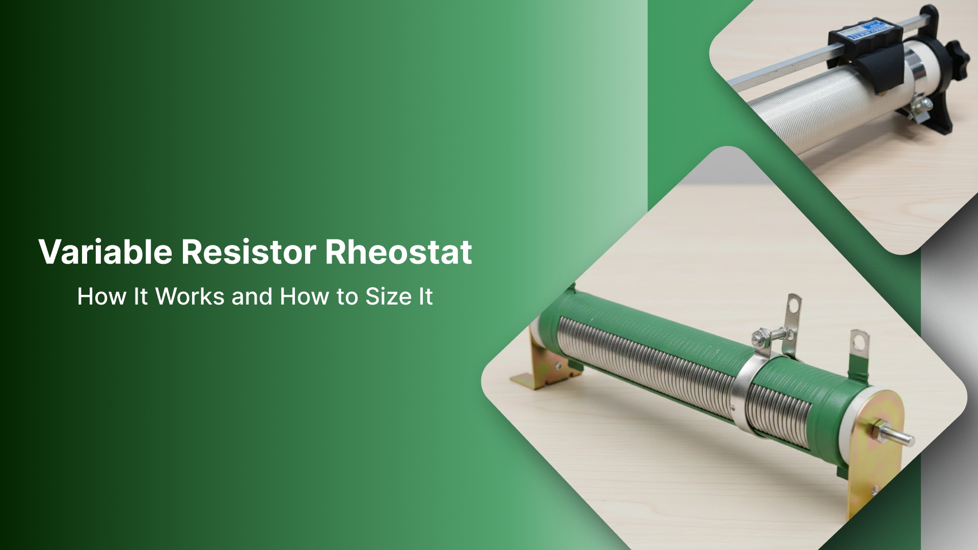
A rheostat is a two-terminal variable resistor used in series to reduce the voltage available to a motor under load.
It “slows” a motor by dropping voltage and burning power as heat, so wattage and duty cycle matter more than the wiring.
This approach is most realistic for certain DC/legacy scenarios. It is not the right speed-control method for most AC induction or 3-phase motors.
Before you do anything, identify the motor type and the control goal (limit vs true speed control).
If you need stable, efficient speed control, use PWM for DC motors or a VFD for AC/3-phase instead of a rheostat.
Before you touch wiring: identify the motor and the control goal
Start with a simple question: what are you actually trying to control? If the goal is repeatable speed, that is a different problem than limiting current, softening startup, or adding a “cap” so the motor can’t run full tilt.
A rheostat can sometimes help with the last two. It rarely delivers the first.
Next, identify the motor type. This decides whether a rheostat approach is even worth considering.
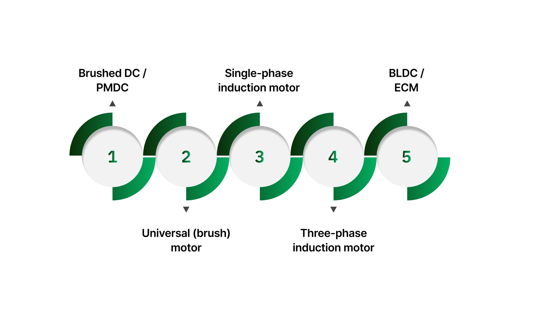
Brushed DC / PMDC
Common in small drives, older equipment, and simple DC systems. A rheostat can change behavior, but it will waste power as heat, and torque will drop as load increases.
Universal (brush) motor
Often found in tools and some older equipment. Speed control is usually handled with purpose-built electronic controls rather than resistive “voltage dropping.”
Single-phase induction motor
Very common in fans, pumps, and general plant equipment. A rheostat is not a proper speed-control method here, and results are typically poor or inconsistent.
Three-phase induction motor
Standard in industrial systems. If you need speed control, the correct tool is typically a drive (VFD), not series resistance.
BLDC / ECM
Electronically controlled motors. External resistance in the line is usually the wrong control method; these motors typically expect a controller input or specific drive electronics.
Once you know the motor type and what you’re trying to stabilize, the decision becomes much faster, and you avoid building a “solution” that can’t behave the way the process needs.
Retrofit decision table: Is a rheostat even the right tool here?
Use this as the fast filter. If the motor type lands in the “not a fit” column, you’ll save time by switching to the right control method instead of fighting symptoms.
Motor type | Rheostat fit? | What you’ll get in practice | Better retrofit option |
|---|---|---|---|
Brushed DC / PMDC | Sometimes | Speed changes with load, torque drops, and the rheostat runs hot under current. Works mainly for light-duty limiting or coarse adjustment. | PWM DC speed controller for stable, efficient control |
Universal motor (brush) | Rarely | Unpredictable results and heat waste. Often noisy control and poor repeatability under load. | Purpose-built universal motor controller (application-dependent) |
Single-phase induction | No (for speed control) | Weak torque, poor control, and inconsistent behavior. It won’t behave like “set speed.” | VFD (if motor/loads allow) or the correct fan/pump method for the application |
Three-phase induction | No | Series resistance is not a practical speed-control method for industrial 3-phase motors. | VFD (standard retrofit approach) |
BLDC / ECM | No | These expect an electronic control input. Added resistance won’t give controlled speed. | Correct the controller/drive or input method specified for the motor |
This assumes typical industrial loads; always follow motor and drive manufacturer guidance.
If a rheostat is even a fit for your motor, the next step is understanding the basic series hookup concept and what that choice does to voltage, torque, and heat.
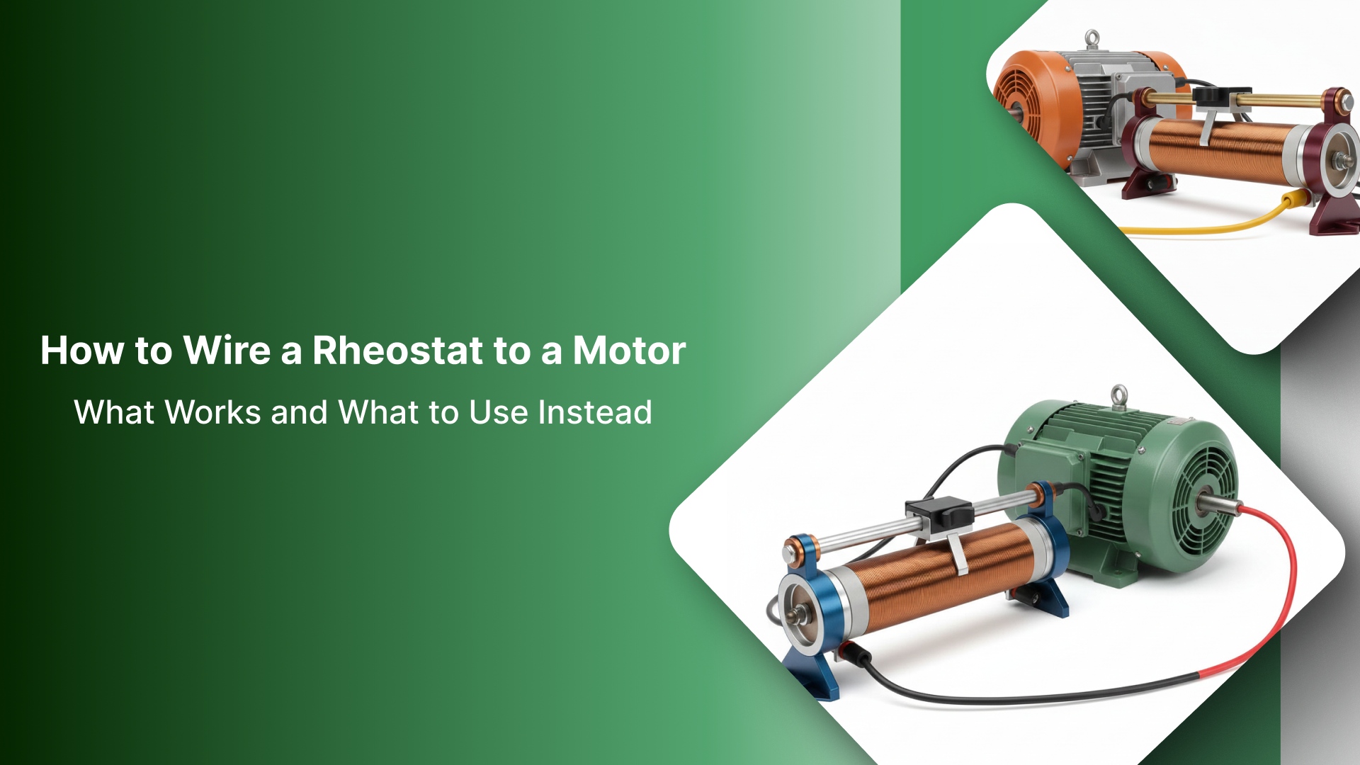
How a rheostat “wires” into motor control
A rheostat is used as a two-terminal variable resistor. In practical terms, the circuit uses the wiper and one end of the resistive element, so turning the adjustment changes the resistance the circuit “sees.”
What “in series” means (the only hookup concept you need)
“In series” means the rheostat is placed in the same current path as the motor, so the motor current must pass through the rheostat. You are not creating a separate control signal. You are inserting adjustable resistance directly into the load path.
What those changes in the real world are straightforward:
As resistance increases, the rheostat creates a larger voltage drop.
With less voltage available under load, the motor typically slows down and loses torque.
The power not delivered to the motor is converted into heat in the rheostat.
Practical warning: this method is load-dependent. If the load changes, the current changes, the voltage drop changes, and the speed shifts with it. Heat is not an edge case here; it’s part of normal operation.
The sizing trap: why “it matched the ohms” still fails
Most rheostat failures aren’t wiring mistakes. They’re heat mistakes. A rheostat slows a motor by dropping voltage, and the “missing” power doesn’t disappear. It gets burned off in the rheostat as heat. If the part can’t shed that heat safely, it drifts, runs erratically, or fails early.
When you’re selecting a replacement, confirm these basics:
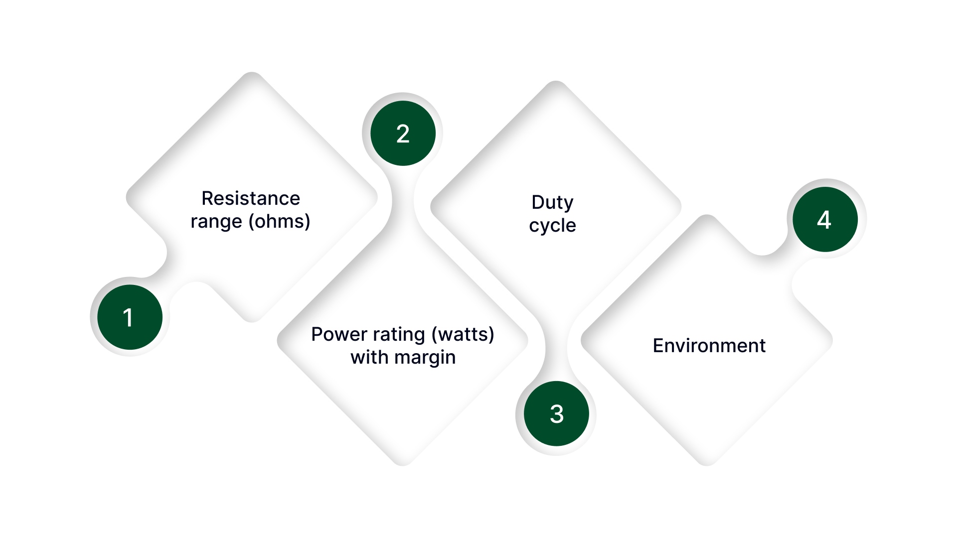
Resistance range (ohms)
The range has to give usable adjustment where the motor actually runs. If all the change happens in a tiny part of the knob travel, the ohms range is usually mismatched.
Power rating (watts) with margin
This is the make-or-break spec. A rheostat can be “correct” in ohms and still be wrong by a mile in wattage. If you expect it to run warm, you are already spending thermal margin.
Duty cycle
There’s a big difference between a rheostat used for occasional setup and one that sits under load for hours. Continuous use needs far more headroom.
Environment
Panel temperature, airflow, nearby heat sources, and vibration all reduce real-world life. A borderline-rated part that survives on the bench often fails in an enclosure.
Simple reality check: if your expected dissipation is anywhere close to the rheostat’s watt rating, don’t “hope it’s fine.” Step up in wattage (and mounting/airflow) or switch to a more efficient control method.
Troubleshooting: Symptoms That Point to the Wrong Setup
These are the patterns that show up most often when a rheostat gets used as a “motor speed control” without matching the motor type and heat load.
It’s basically off / full speed
This usually means the approach is wrong for the motor, the rheostat value isn’t appropriate, or the system is so load-sensitive that a small change pushes it from “can’t turn” to “runs.”
The rheostat gets hot fast
That’s a wattage problem, a current problem, or both. The rheostat is being asked to burn off more power than it can safely dissipate in the enclosure it’s installed in.
It won’t hold a steady speed
This is normal behavior for resistive control. As the load changes, the current changes, the voltage drop changes, and the speed moves with it. If the process needs repeatable speed, you need a proper controller.
The motor feels weak or stalls
That’s torque loss from reduced available voltage under load. The rheostat isn’t “regulating” torque; it’s reducing what the motor can draw when the work increases.
If you’re seeing any of these symptoms, don’t keep “tuning the knob,” treat it as a motor-type or heat-capacity mismatch and switch to the right control method.
When You Need Real Speed Control: What to Use Instead
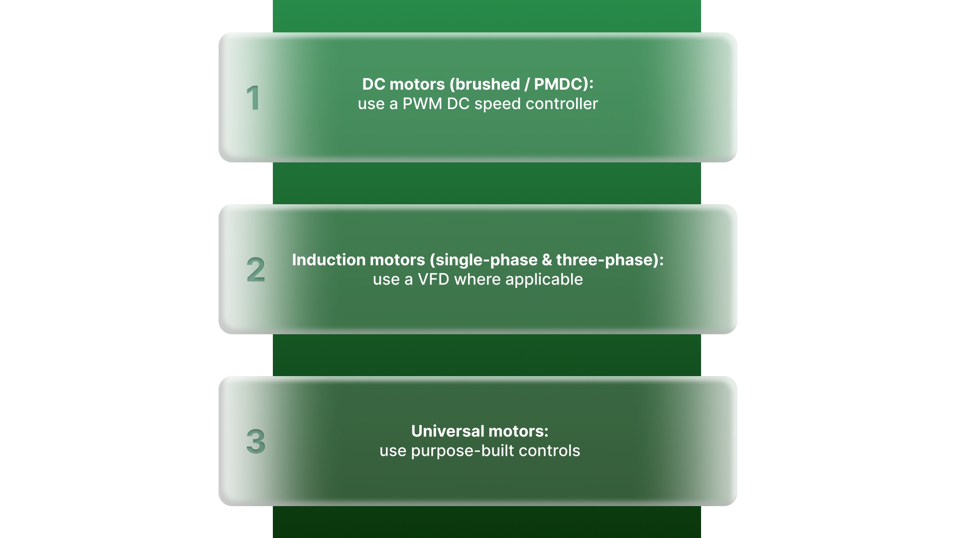
If the process needs a speed you can set and repeat, resistive control is usually the wrong tool. These options are what most teams use when they want stable results without turning excess power into heat.
DC motors (brushed / PMDC): use a PWM DC speed controller
PWM control is far more efficient than a rheostat and typically holds speed better under changing load. It’s also easier to make repeatable once you’ve dialed in the operating point.
Induction motors (single-phase and three-phase): use a VFD where applicable
A VFD is the standard retrofit approach for controlled speed on induction motors. It’s designed for the job and avoids the weak torque and heat waste you get from “voltage-dropping” methods.
Universal motors: use purpose-built controls
Universal motors don’t behave like DC or induction motors in practice. If you need controllable speed, use a controller designed for that motor and application rather than trying to force a rheostat to act like a drive.
If you still need an adjustable “knob” because the application is intentionally resistive, not true speed control, the next question is whether that adjustment has to be remote, repeatable, or automated. That’s where motorized resistance control can make sense.
When motorized resistance control actually makes sense
A motorized rheostat makes sense when the resistive method is already the right approach and the real problem is consistency.
Remote adjustment with the panel closed
Useful when the setting is inside a guarded enclosure or the knob is simply not accessible during operation.
Repeatable settings for changeovers and test setups
Helps when operators need the same setting every time for recipes, trials, or standardized runs.
Controlled movement instead of “bump it until it feels right.”
Motorized adjustment reduces overshoot and operator variation, especially when small changes matter.
Only when resistive control is intentional and properly rated
Motorizing a marginal rheostat does not fix the core issue. Wattage, duty cycle, and heat management still decide whether the solution survives.
Once you know motorized resistive control is actually the right fit, the next step is matching the unit to the real specs, ohms, watts, duty cycle, and motor type so it moves predictably and survives the heat. That’s where On Line Controls comes in.
Where On Line Controls fits in real retrofits
Once the method is confirmed, the hard part is matching ratings and mechanics so the retrofit survives real load and heat.
On Line Controls builds hardware specifically for these retrofit scenarios, including:
Motorized rheostats for applications that truly require variable resistance in the load path, where wattage and heat dissipation are part of the design requirement.
Motorized potentiometers (MotorPots) for automating setpoints and control signals are often the better solution when the “knob” is actually feeding a controller input and you need remote or repeatable adjustment.
What this solves in the field:
Legacy replacements where you need the right match on resistance, wattage, motor type, and mounting.
Repeatable adjustment for changeovers and standardized settings, without relying on “whoever is on shift.”
Remote control when the adjustment point is inside a closed panel or hard-to-reach location.
If you’re retrofitting a manual knob, start with the basics you can verify (motor type, ohms, watts, duty cycle, and any part number). Then use On Line Controls’ motorized rheostat and MotorPot pages to narrow the closest match. If you want the fastest confirmation, get in touch with On Line Controls for a direct recommendation.
Conclusion
A rheostat-to-motor “wiring” job only goes smoothly when the application is a true fit. Start by identifying the motor type and what you’re trying to stabilize. If the process needs repeatable speed under changing load, a rheostat is usually the wrong tool.
It will drop voltage, waste power as heat, and the results will move with the load.
If resistive control is intentional and properly rated, then the win comes from correct sizing and consistent adjustment. That means choosing a rheostat with real thermal margin and a setup that doesn’t depend on trial-and-error at the panel.
And if the setting needs to be remote or repeatable, motorized options can make the retrofit behave like a controlled system instead of a “turn it until it feels right” workaround.
FAQs
Can a rheostat control motor speed safely?
Sometimes, but only in the right use case. A rheostat changes motor behavior by adding series resistance, which creates heat and reduces available torque. It can be acceptable for certain low-power or legacy scenarios where resistive control is intentional and properly rated. For repeatable speed control, it is usually not the right tool.
Will a rheostat work on an AC induction motor?
Not as a proper speed-control method. Induction motors typically need a drive-based approach for controlled speed. A rheostat-style “voltage drop” approach usually leads to weak torque and inconsistent results under load.
What wattage rheostat do I need for a motor?
Choose based on how much power the rheostat must dissipate as heat, with a margin for real operating conditions. If your expected dissipation is close to the rheostat’s watt rating, it’s under-sized for continuous use. Duty cycle, enclosure temperature, and airflow all affect how much margin you need.
Why does the rheostat get hot?
Because that’s how it works. Any power that doesn’t go to the motor is burned off in the rheostat as heat. The more current flows and the more voltage is dropped across the rheostat, the more heat it must dissipate.
What should I use instead of a rheostat for speed control?
For DC motors, use a PWM DC speed controller. For induction and three-phase motors, use a VFD where applicable. For other motor types, use the control method designed for that motor and application rather than relying on series resistance.