A DC voltage potentiometer can appear to be a simple component. In industrial control panels, however, it functions as a setpoint device, and many field issues come from treating it like a generic “voltage adjustment” part.
In practice, these potentiometers are often used to generate a 0–10 V (or 1–10 V) reference for a drive input, controller, or PLC analog channel. When the reference scheme, wiring method, or resistance value is mismatched, the failure modes are consistent: the setpoint will not reach full scale, the signal becomes unstable or noisy once installed, or the control behaves correctly on the bench but drifts in service.
This guide explains the most common DC reference arrangements, how to select the correct electrical and mechanical configuration, how to wire for a stable reference signal, and a short verification checklist to confirm the installation is ready for operation.
Key Takeaways
A DC voltage potentiometer is a voltage divider; it requires an existing reference supply and does not generate voltage on its own.
Specify the potentiometer to the receiving input and reference source (input impedance, required range, taper, and power rating), not by defaulting to a generic resistance value.
Wire for stability and predictable behavior: protect wiper integrity, follow disciplined grounding/shielding practices, and define the fail condition if the wiper opens.
Verify performance at the panel: confirm full-range output, no dropouts or noise during a slow sweep, and setpoint stability under normal operating conditions.
What “DC voltage potentiometer” mean in industrial controls
In industrial environments, a DC voltage potentiometer is a passive voltage divider, not a power-generating component. It scales an existing DC reference, typically 5V, 10V, or 24V, into a variable setpoint signal, such as 0–10 V, 1–10 V, or 0–5 V.
What it is: A manual or motorized interface that provides a reference for VFD speed, DC drive torque, or PLC analog inputs.
What it is not: A rheostat. If your application requires dissipating heat or carrying motor current directly, you are looking for a power resistor, which has entirely different thermal and mounting requirements.
Where the setpoint signal typically goes
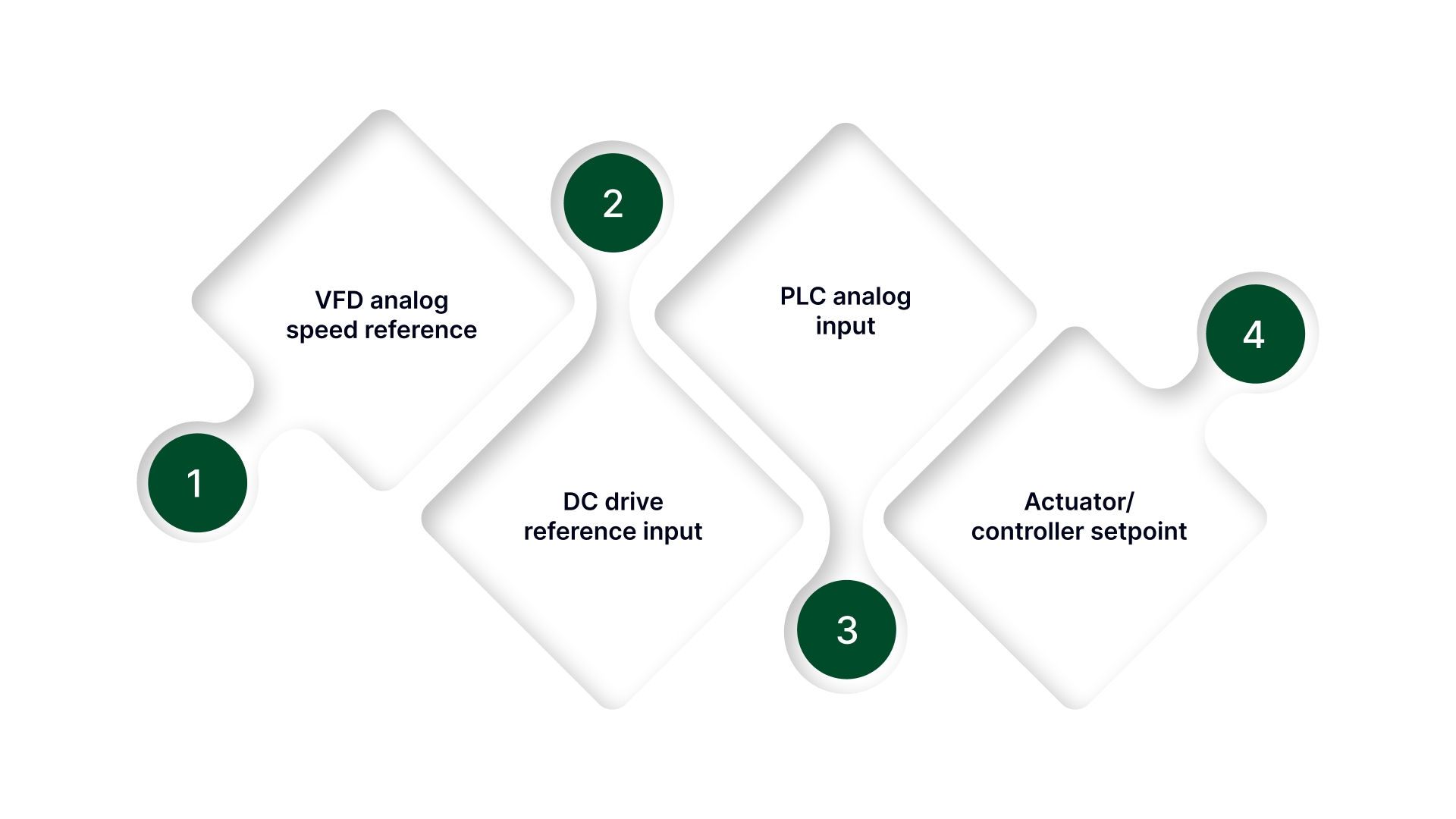
VFD analog speed reference (often 0–10 V or 4–20 mA via a converter)
DC drive reference input
PLC analog input (for operator setpoint or feedback scaling)
Actuator/controller setpoint inputs (position/pressure/flow controllers)
Why does the ambiguity cause failures
Buying a “pot” without confirming the system type can lead to installing a device that is electrically or mechanically wrong: incorrect reference expectations, wrong taper, unstable signal behavior, or a misfit that introduces noise and drift.
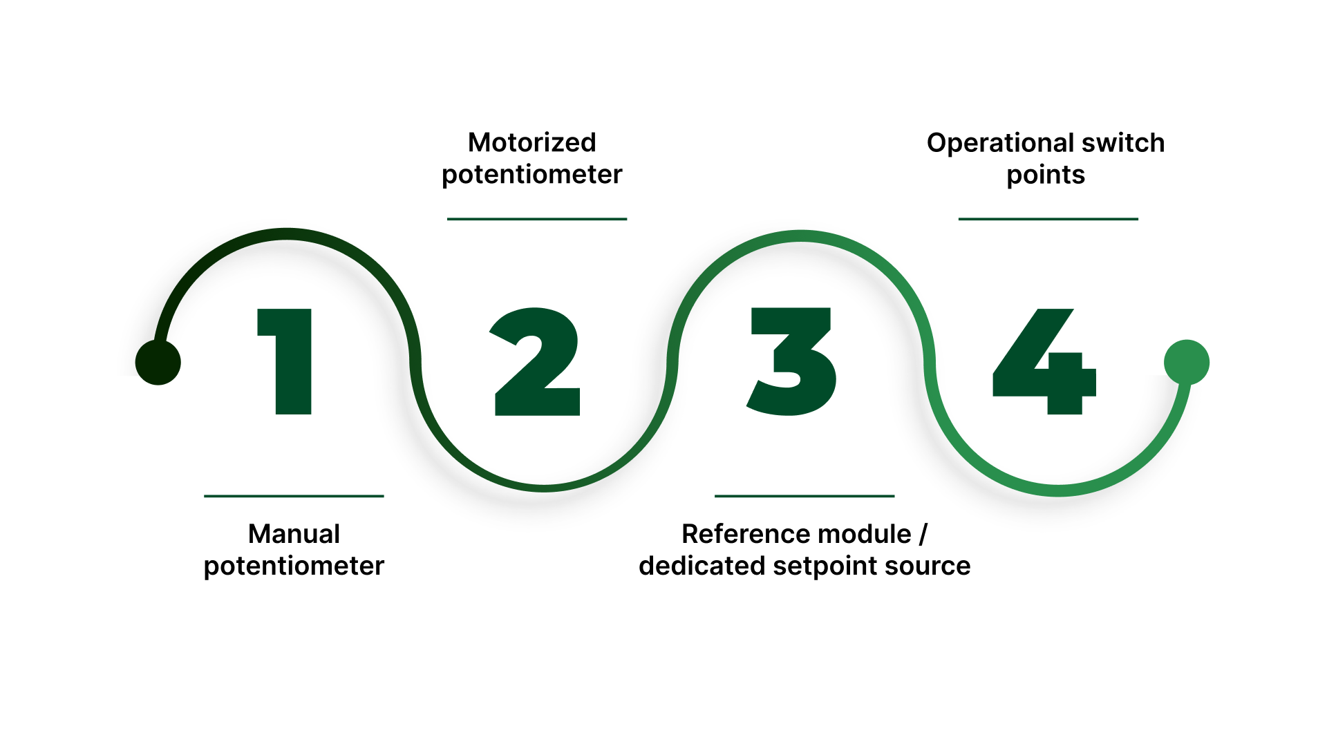
Once you are confident the application is a DC setpoint divider, the next decision is whether the job calls for a manual potentiometer, a motorized potentiometer, or a dedicated reference/setpoint module based on repeatability, access, and how the setpoint must behave in operation.
Choose the right setpoint device (manual pot vs motorized pot vs reference module)
A “DC voltage potentiometer” requirement is often written as if the hardware choice is obvious. In practice, device selection is a control decision: who needs access, how often the setpoint changes, whether the setting must be repeatable, and whether the panel environment invites drift or tampering.
Choosing the right setpoint device upfront prevents the two common outcomes: a knob that should not be touched or a setting that cannot be repeated.
Manual potentiometer
This is a best fit when the setpoint is adjusted infrequently, access is safe and intentional, and there is no strong requirement for documented repeatability.
Typical use: Local operator trim, commissioning adjustments, or stable processes where “close” is acceptable.
Watch-outs: Accidental bumping, unauthorized adjustment, wear over time, and inconsistent operator technique.
Motorized potentiometer
This is used when the setpoint must be adjusted without opening a guarded panel, from a remote location, or in a controlled manner during changeovers.
Typical use: Hard-to-reach enclosures, safety-guarded equipment, recipe-driven processes, or applications where the setpoint needs to be moved but not handled directly.
Watch-outs: Requires a defined control method (manual remote control or automation), and installation must support stable, repeatable movement without introducing noise at the wiper.
Reference module / dedicated setpoint source
A reference model is an apt fit when the setpoint must be stable, documented, and resistant to drift, or when the process cannot tolerate “knob variability.”
Typical use: Critical setpoints, tamper-resistant installations, compliance-driven processes, or systems where the reference must remain consistent across shifts and maintenance events.
Watch-outs: May require integration effort (signal scaling, documentation, and commissioning), but offers the cleanest long-term stability.
Operational switch points
Access constraints: if opening the panel is restricted, lean motorized or module-based setpoint.
Repeatability requirement: if the setting must return to the same value reliably, avoid a basic manual knob.
Risk of accidental adjustment: if a bump, vibration, or casual “tweak” creates risk, use guarding, remote adjustment, or a module.
Changeover frequency: frequent changes favor motorized control or a module over a manually dialed potentiometer.
Once the device type is chosen, the next avoidable failure is ordering a potentiometer value that does not match the receiving input, so the next step is specifying the pot correctly (input impedance, range, taper, and expected fail behavior).
How to Spec a DC Setpoint Potentiometer (Value, Taper, and Construction)
Most setpoint issues trace back to specification mismatches: the potentiometer value loads the input, the taper produces a non-usable adjustment range, or the construction can’t tolerate the environment. This section ties the potentiometer specification to the receiving input and panel conditions.
A DC setpoint potentiometer is only as stable as the combination of input loading, mechanical construction, and environment.
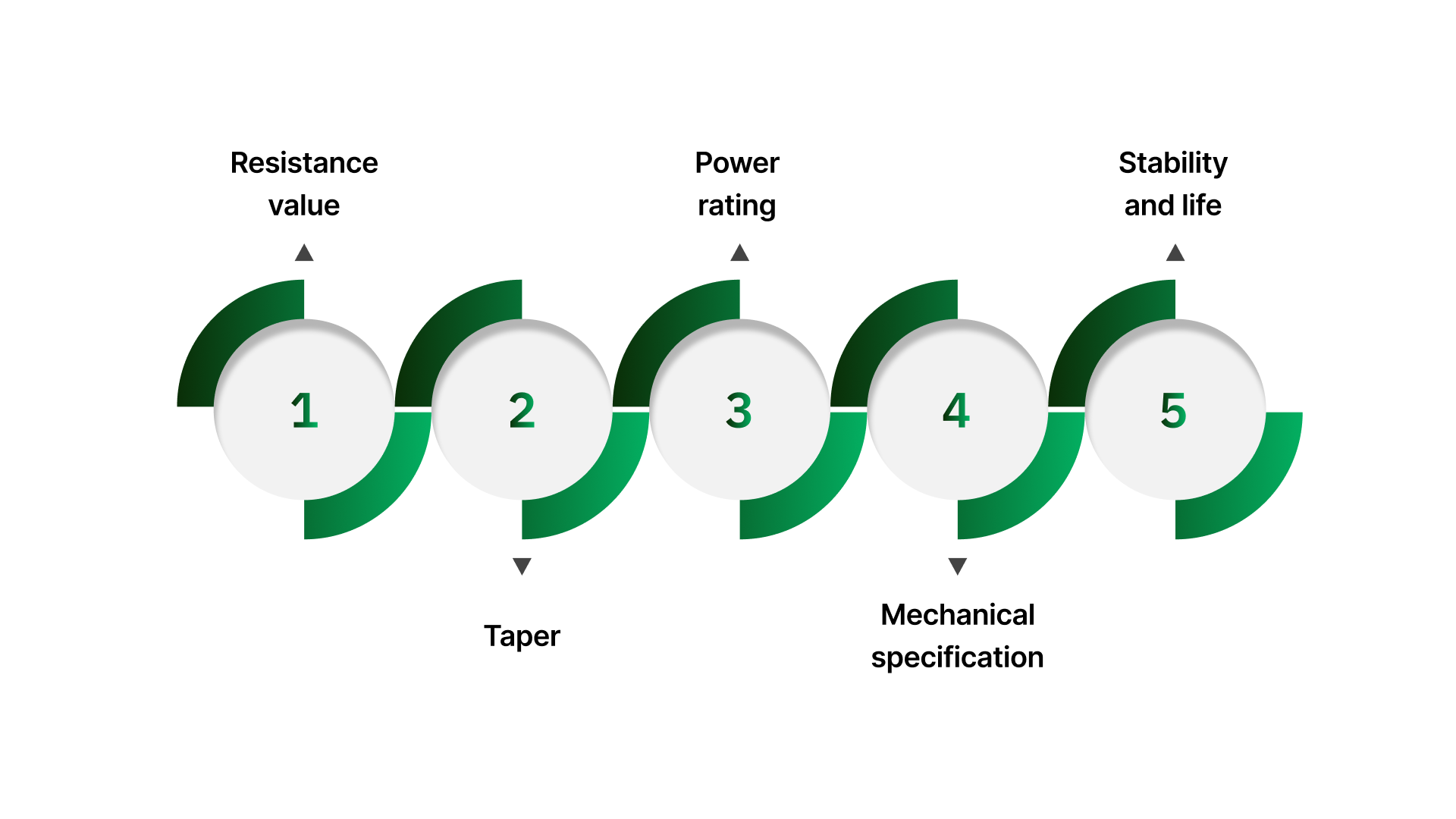
Resistance value: Choose it to match the receiving input
Start with the receiving device’s analog input documentation (VFD, drive, PLC, controller): look for input impedance and any guidance on recommended potentiometer value.
The practical goal is to keep the potentiometer’s effective source resistance low enough that the input does not “load” it and compress the usable range.
If the input impedance is low (or the input is noisy), overly high resistance values can make the wiper signal more sensitive to interference and contact variation.
When no recommendation is available, treat “10 kΩ” as a starting point only—confirm the input’s impedance and allowable source resistance so the full setpoint range is usable and stable.
Taper: Linear vs logarithmic
Linear taper is the default for industrial analog setpoints because it gives a proportional change in the divided voltage across knob travel.
Log/audio taper is typically the wrong choice unless the receiving device explicitly expects it or the application has a defined non-linear response requirement.
If operators complain that “all the change happens at one end,” confirm taper and confirm the receiving input scaling. This symptom is frequently misdiagnosed as a value problem.
Power rating: Low-power in normal use, but confirm the reference and fault expectations
Most setpoint potentiometers run at very low power because they divide a reference signal, not drive a load.
Still verify: reference supply voltage, any series resistors, and what happens during miswiring or fault conditions (for example, if the pot could see more than the expected reference).
If the setpoint circuit is not purely a high-impedance input (for example, it sources/sinks current unexpectedly), treat that as a design red flag and correct the interface before selecting the potentiometer.
Mechanical specification: Fit, interface, and sealing
Specify the mounting package that matches the panel and operator hardware:
Bushing/shaft style and thread details
Panel thickness and thread engagement
Shaft diameter/length and knob interface (D-flat, keyed, set-screw, etc.)
If the panel is exposed to washdown, dust, oils, or condensation, specify appropriate environmental sealing and materials (including shaft seal considerations where relevant).
Stability and life: Specify for real adjustment and vibration, not “bench use.”
Wiper quality and construction matter because instability presents as dropouts, jitter, or drift at the setpoint.
Align expected life to reality: number of adjustments per shift, whether the knob is bumped, and whether the enclosure sees vibration.
If vibration exposure is non-trivial, avoid “light duty” constructions and plan for mechanical anti-rotation and a knob/shaft interface that will not creep.
With the correct specification in hand, the next determinant is wiring because even a correctly chosen potentiometer will behave poorly if the wiper lead is noisy, grounding is inconsistent, or shielding is terminated incorrectly.
Wire it for a stable DC setpoint
A DC voltage potentiometer in controls service is typically used as a voltage divider that feeds an analog input. When setpoints wander, jump, or “won’t repeat,” the cause is often wiring discipline reference integrity, wiper continuity, and noise coupling rather than the potentiometer itself.
Voltage divider wiring
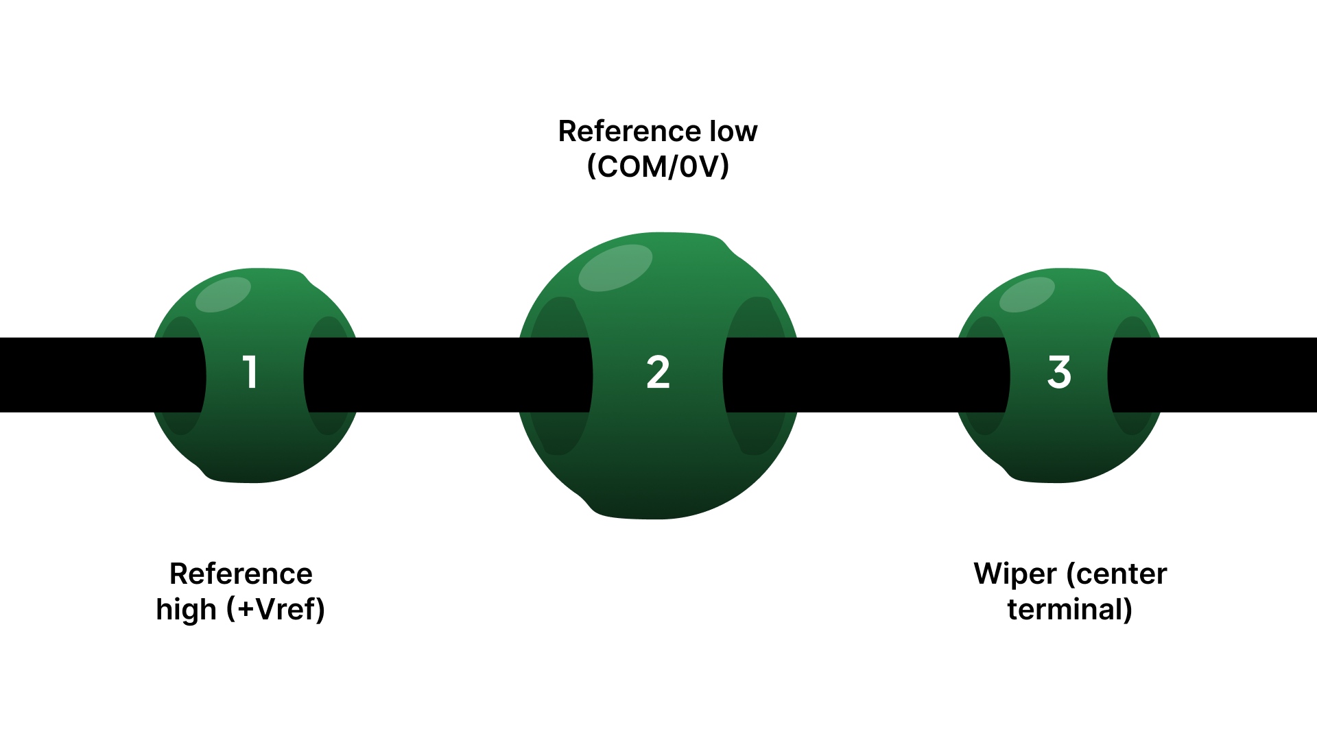
Most 0–10 V (or similar) setpoint schemes follow the same structure:
Reference high (+Vref) → one outer potentiometer terminal
Reference low (COM/0V) → the other outer potentiometer terminal
Wiper (center terminal) → the analog input signal terminal
This creates a controllable fraction of the reference voltage at the wiper.
2-wire vs 3-wire conventions
Not all devices label inputs consistently. Before landing wires, confirm whether the receiving device expects:
3-wire divider input (typical): separate +Vref, COM, and AI (signal)
2-wire/“signal + common” arrangements: where the reference is internal, and the device expects a different scheme (often documented as a specific terminal pairing)
If the drive/PLC documentation shows a dedicated reference output, treat it as a divider application unless stated otherwise.
Follow the receiving device manual and site wiring standards for analog reference routing, grounding, and shield termination.
Wiper integrity and “fail direction” behavior
A key reliability question is: What does the system do if the wiper opens or becomes intermittent?
Common outcomes include:
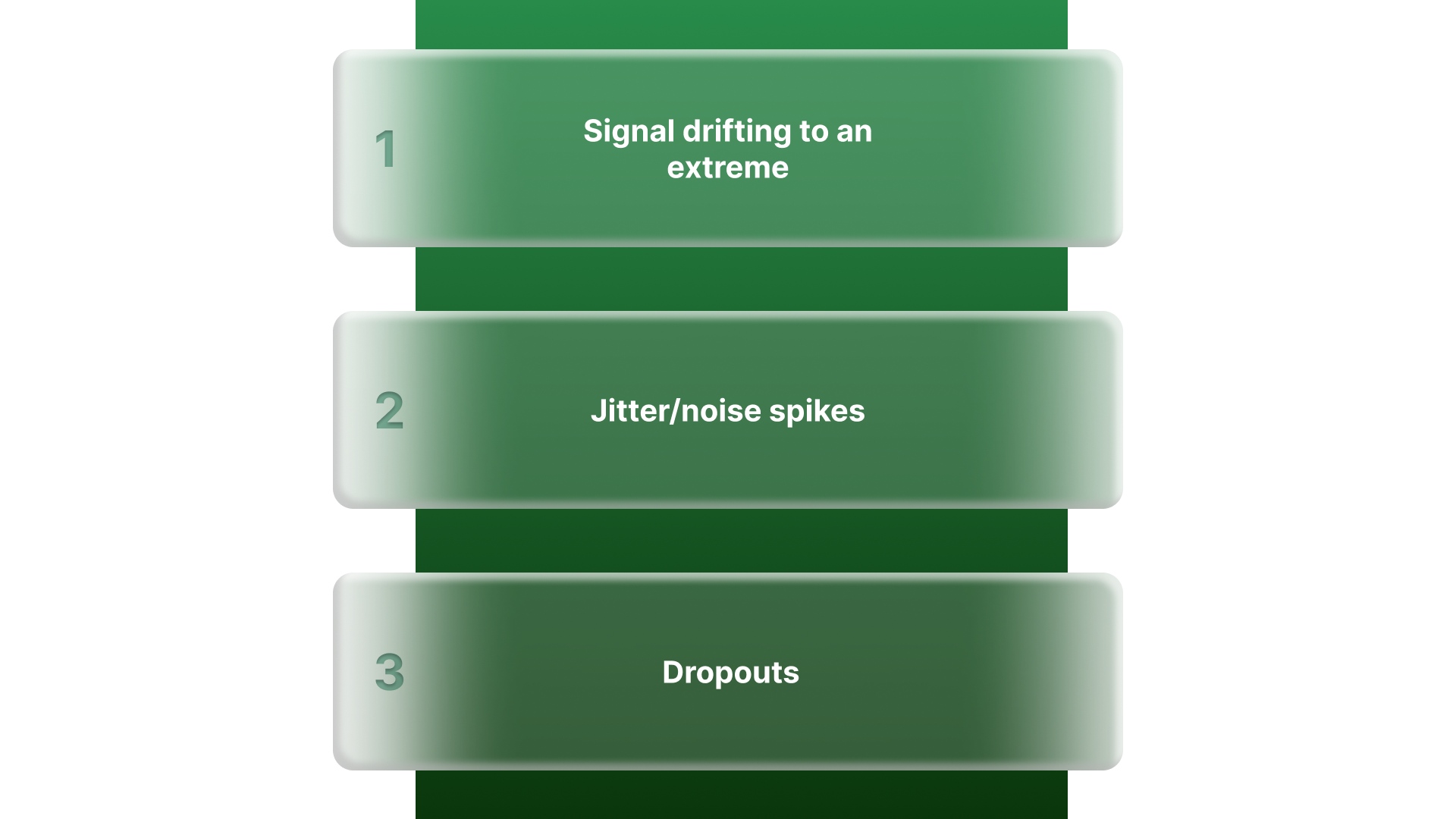
Signal drifting to an extreme (depending on how the input is biased internally)
Jitter/noise spikes that look like process instability
Dropouts that resemble a bad analog input
Where the application risk is meaningful, prefer wiring and input configurations that bias toward the safer default state (based on the receiving device’s documented behavior).
Noise control basics that prevent drift and jitter
Most “noisy setpoint” problems are avoidable with a few control-standard practices:
Route setpoint wiring away from high-noise conductors (motor leads, VFD output cables, contactors, transformer primaries)
Use shielded cable where the environment warrants it and terminate the shield per site standard, commonly at one end only, to reduce loop risk
Maintain a clean reference return (reference low/COM) and avoid sharing it with high-current returns unless the design explicitly calls for it
Terminations and mechanical strain control
Loose or stressed connections can create symptoms that look like electrical noise:
Provide strain relief so conductors cannot tug on terminals during door motion or service activity
Avoid unsupported terminal “hanging weight” and tight bends that fatigue conductors
Treat crimps and screw terminations as setpoint-critical; a marginal termination can behave like an intermittent wiper
Panel-level confirmation
Do these checks at the drive/PLC/controller terminals (not only at the potentiometer), because loading and noise often show up only at the receiving input.
Confirm full range at the input: With the reference energized, verify minimum and maximum setpoint voltage at the analog input terminals match the expected range (for example, ~0–10 V or ~1–10 V).
Slow sweep test: Rotate the knob slowly end-to-end and confirm the input changes smoothly, no dead spots, dropouts, or sudden jumps.
Hold test with the door closed: Set a mid-range value, close the panel, and confirm the input reading remains stable over time (no drift once wiring is dressed and the enclosure is in its normal state).
Noise exposure check: Observe the input while nearby equipment cycles (contactors, motors, drives). If the reading moves when other loads switch, treat it as a wiring/shielding/ground reference issue.
Record what matters: Note the wiring convention used (+Vref/COM/wiper), shield termination approach (per site standard), and the final setpoint reference position for repeatability.
With specification and wiring confirmed at the receiving input, the remaining risk is mechanical: mounting, protection, and access choices that determine whether the setpoint holds in service.
Mounting and protection so the setpoint stays serviceable
A DC voltage potentiometer may be electrically correct and still fail in the field if the installation allows rotation, knob drift, terminal stress, or unsafe access.
Treat mounting as part of the control function: the setpoint must remain stable, serviceable, and protected from routine panel vibration and operator interaction.
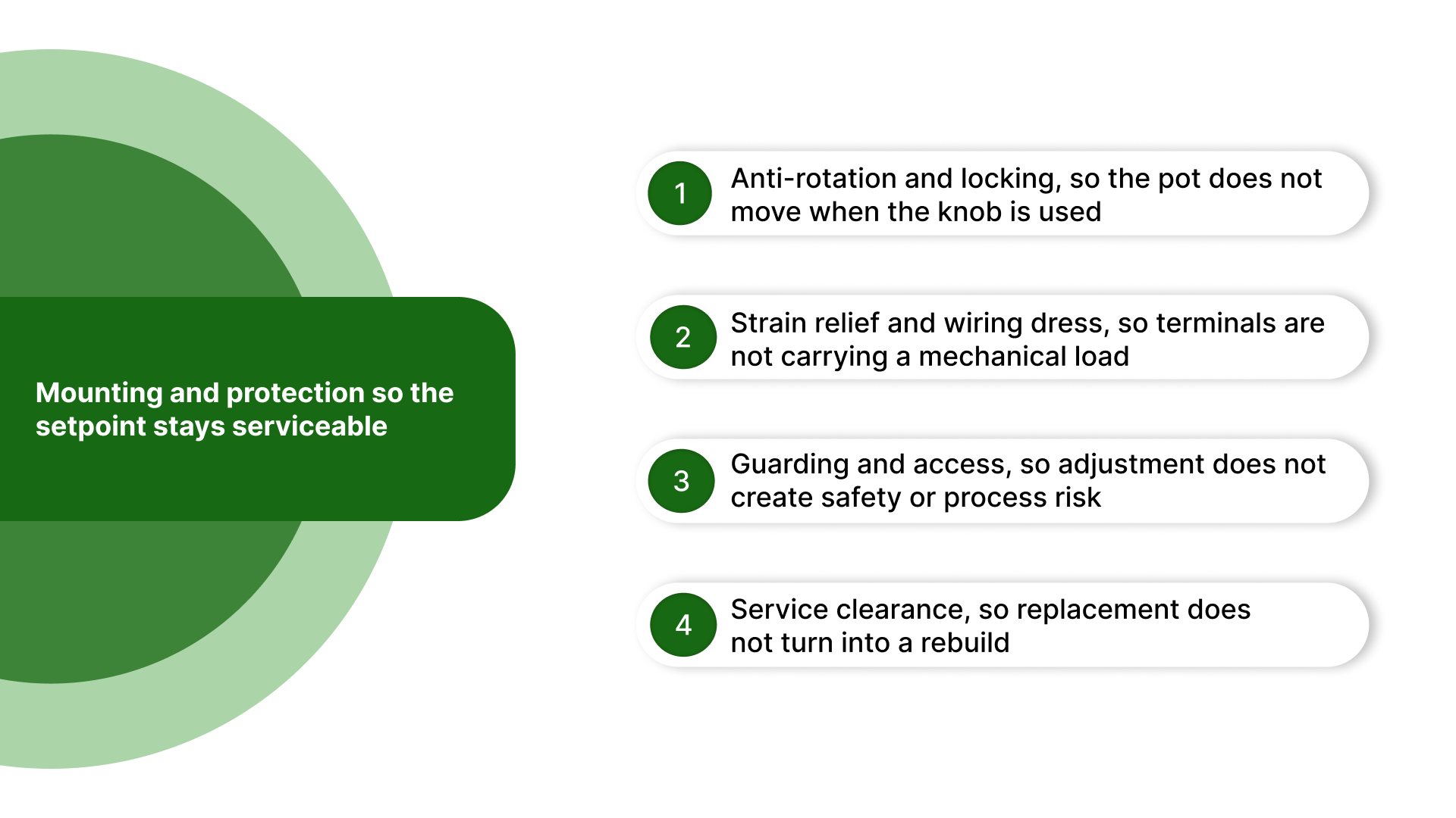
Anti-rotation and locking, so the pot does not move when the knob is used
Use the anti-rotation feature if provided (tab washer, D-flat, keyed bushing, or panel feature). If the bushing can rotate, the wiring becomes a torsion point and will loosen over time.
Apply proper locking hardware: lock washer and/or jam nut when vibration, frequent adjustments, or stiff wiring are present.
Follow basic torque discipline: tighten the mounting nut to secure the bushing without distorting the panel or overstressing the bushing threads.
Strain relief and wiring dress, so terminals are not carrying a mechanical load
Provide strain relief close to the device, so wire movement cannot tug on terminals during door opening/closing or vibration.
Maintain a service loop where the potentiometer is door-mounted or located near a hinge path, so motion does not flex the terminal connections.
Dress wiring so conductors do not rub on sharp edges, pinch points, or moving parts, and so they do not pull the potentiometer body out of alignment.
Guarding and access, so adjustment does not create safety or process risk
If an exposed knob can be bumped or adjusted unintentionally, use guards, recessed mounting, or a locking knob.
Where access is restricted for safety or process reasons, consider remote adjustment (motorized potentiometer) or relocating the operator interface to a safer point.
If the setpoint must not be changed casually, use a tamper-resistant approach (guarding, locking hardware, or controlled access) rather than relying on markings alone.
Service clearance, so replacement does not turn into a rebuild
Leave enough space for tool access to the mounting nut and terminals, and enough clearance to remove the device without dismantling adjacent ducting or terminal blocks.
Ensure the installation supports inspection: visible terminals, readable labeling, and the ability to confirm wiring condition without disassembly.
If the panel is crowded, prioritize clearance for the potentiometer and its terminations. Setpoint faults are often intermittent and require access to diagnose.
With mounting locked down, the remaining risk is almost always at the receiving input: range, stability, and noise under real panel conditions. Use the panel-level confirmation checks above as the acceptance gate before sign-off.
On Line Controls: Spec confirmation when the setpoint won’t stay stable
If your panel-level checks show compressed range, unstable readings, or a setpoint that changes once the door is closed, the next step is typically to confirm the setpoint device and specification against the receiving input and the panel environment.
Where On Line Controls can help
Confirm the correct setpoint approach (manual potentiometer, motorized potentiometer, or a dedicated reference source) based on access, guarding, and repeatability requirements.
Match the electrical spec to the input so the signal behaves correctly in service: value vs input impedance, expected setpoint range (0–10 V / 1–10 V / 0–5 V), and taper where it matters.
Match the mechanical package to the panel so it installs cleanly and remains serviceable: shaft/bushing style, mounting hardware, clearance, and terminal orientation.
Reduce drift and intermittents caused by installation realities, including wiper integrity risk, termination quality, and noise exposure that only appears once wiring is dressed and the enclosure is operating normally.
A setpoint that looks correct at the potentiometer but not at the receiving input is almost always a loading/wiring discipline / mechanical stability issue, solved faster by confirming the configuration than by repeated tuning at the controller.
Contact On Line Controls with the receiving input type and your current pot value/wiring scheme, and we’ll confirm a setpoint configuration that stays stable at the drive/PLC terminals.
Conclusion
A DC voltage potentiometer is only as reliable as the system around it: the receiving input’s impedance, the reference scheme, wiring and shielding discipline, and the way the device is mounted and protected.
When you specify the potentiometer to the input, wire it as a voltage divider with defined wiper behavior, and confirm performance at the receiving terminals under normal panel conditions, the setpoint remains stable and repeatable rather than becoming a source of drift, noise, and rework.
FAQs
What is a DC voltage potentiometer used for?
In industrial panels, it is commonly used as a setpoint device, a voltage divider that provides an adjustable DC reference to a drive input, PLC analog input, or controller.
Can a potentiometer create 0–10 V by itself?
No. A potentiometer does not generate voltage; it divides an existing reference supply. A stable reference (such as 10 V) is required, and the wiper provides a fraction of that reference.
What resistance value should I use for a 0–10 V control input?
It depends on the receiving device’s input impedance and any published guidance for allowable source resistance. Selecting “a generic value” can compress the range or increase noise sensitivity, so confirm against the drive/PLC documentation.
Why does my setpoint jump or become unstable when equipment switches on?
Common causes include poor shield termination, routing the setpoint wiring near high-noise conductors, inconsistent reference return practices, or a high-resistance setpoint circuit that makes the wiper signal more susceptible to interference.
When should I use a motorized potentiometer instead of a knob?
Use a motorized potentiometer when the setpoint must be adjusted remotely, protected from tampering, or returned to a repeatable position during changeovers, especially when panel access is restricted for safety or reliability.