Do not put a potentiometer across 24V and assume the wiper is a valid setpoint.
In most control panels, 24V is the control power. The receiving input is usually designed for a specific reference method, commonly a 0–10V divider from a dedicated reference output, a 4–20 mA loop, or a digital setpoint.
When those are confused, the result is not subtle: the setpoint compresses, noise appears under normal switching, and “bench-correct” behavior fails in the enclosure.
This guide explains what “24V potentiometer” typically means, how to identify your case (A/B/C) in minutes, and what to use so the receiving device sees the setpoint it was designed for.
Key Takeaways
Treat ‘24V potentiometer’ as a signal-interface question, not a parts question.
Identify the receiving input first: voltage, current, or non-analog.
Use the device’s reference method when provided (often +10V/COM/AI).
If only 24V is available, use a proper interface matched to the input.
What do people mean by “24V DC potentiometer” in panels
When someone asks for a “24V DC potentiometer” in an industrial panel, they’re usually not describing a correct analog reference scheme. They’re describing the environment: 24VDC control power is readily available in the cabinet, and they want a knob-style setpoint that “gives a voltage.”
In most control architectures, 24VDC is supplied for PLC I/O, sensors, relays, and control circuits. The setpoint input to the drive, controller, or PLC is designed for is typically something else: a dedicated +10V reference divider, a 0–10V/1–10V input, a 4–20 mA loop, or a digital setpoint.
That distinction matters because using 24V as the analog reference is one of the fastest ways to create predictable problems: compressed knob range, unstable readings, or a setup that looks fine on the bench but fails once it’s landed on the actual receiving terminals and routed through the panel.
Why is the phrase misleading
In panels, “24V” usually means available control power, not the analog reference voltage the receiving device is designed around.
A potentiometer does not generate a signal; it divides a reference. If the reference is wrong (or the input isn’t meant for voltage division), the control will not behave correctly.
In practice, “24V potentiometer” usually means “a knob setpoint in a 24VDC panel,” not that the input is designed for a 0–24V wiper.
The receiving input families, this usually feeds
Before you pick hardware or wiring, identify the receiving side. In the field, the “knob setpoint” usually feeds one of these:
0–10V / 1–10V voltage input
4–20 mA current input
Digital/comms setpoint (Modbus, Ethernet/IP, Profibus, etc.)
Internal keypad/HMI reference (parameter-based setpoint with lockout)
PLC analog input (knob goes to PLC, PLC generates the final setpoint)
Once you agree on what the knob is supposed to feed, the next step is identifying which of three field cases you’re in (A/B/C), because the correct solution depends entirely on what those receiving terminals actually are.
Identify your case (A/B/C) and use the correct setpoint method
Most “24V potentiometer” issues are solved faster by classifying the receiving input than by swapping parts. Use the steps below to identify what the device actually expects, then apply the matching solution path.
60-second identification at the receiving terminals
Check the drive/PLC/controller terminals where the setpoint lands (not just where 24V is available):
Look for a dedicated analog reference output near the analog input terminals (often labeled +10V, 10V, Vref, with COM/0V/AGND nearby).
Confirm whether the input is labeled as AI/V-in/0–10V, I-in/4–20mA, or something digital (comms, keypad/HMI reference).
If you have a manual, use the wiring example page for “analog speed reference / external setpoint.”
If it’s a PLC card, confirm whether the channel is a voltage input, a current input, or configurable.
If the “setpoint” is a parameter or keypad value, you may not have an analog setpoint input at all.
Case A vs Case B vs Case C
Case | What you see in the panel | What it means | Correct setpoint method | Common wrong moves to avoid |
|---|---|---|---|---|
Case A | +10V (or Vref) + COM/0V + AI terminals | The device expects a potentiometer voltage divider | Use a standard pot: +10V → end, COM → end, wiper → AI | Using 24V as the divider reference because it’s “available.” |
Case B | Only 24V control power available, but the input is 0–10V or 4–20mA | You need an interface, not a raw pot across 24V | Use a signal conditioner/transmitter / PLC AO/setpoint module matched to the input type | Putting a pot across 24V and feeding a 0–24V wiper into a 0–10V input |
Case C | Input is not a voltage setpoint (current-only, digital/comms, internal reference) | A potentiometer is not the right interface | Use the correct source: 4–20mA transmitter, PLC/comms setpoint, or internal keypad/HMI reference | Building “scaling hacks” to force a pot into a non-voltage input |
Case A: Device provides a 10V reference (the intended potentiometer use)
If you have +10V / COM / AI terminals, the simplest and most reliable setpoint is a standard voltage-divider potentiometer:
Wire +10V → one outer terminal, COM/0V → the other outer terminal, and wiper (center) → AI.
If the device uses 1–10V, confirm whether it expects a minimum bias (some systems don’t want a true 0V command).
Keep the setpoint wiring routed away from high-noise conductors so the divider stays stable at the receiving terminals.
If your panel does not provide a reference output and you only have 24V control power, you are in Case B.
Case B: Only 24V is available (how to get a usable setpoint without creating problems)
If the input expects 0–10V or 4–20mA but you only have 24V control power, the correct approach is to generate the signal the way the input expects:
If the input is 0–10V: use a 24V-powered signal conditioner or a PLC analog output configured for 0–10V.
If the input is 4–20mA: use a 24V loop-powered transmitter/source designed to output 4–20mA.
When repeatability or protection matters, use a dedicated setpoint module (instead of an exposed knob powered from 24V).
Avoid the tempting shortcut: a 0–24V wiper is often outside the input range and creates unstable or compressed behavior, even if it doesn’t immediately damage anything.
If the receiving terminal is not a voltage input at all, you are in Case C.
Case C: The input is not 0–10V (do not force a potentiometer)
If the device does not accept a voltage divider setpoint, a potentiometer becomes a workaround rather than a solution.
Use the correct setpoint method based on what the device actually accepts:
4–20mA only: use a proper current source/transmitter (or PLC AO configured for current).
Digital/comms setpoint: use a supported protocol (via PLC/HMI) rather than trying to “fake” analog.
Internal keypad/HMI reference: use the device’s internal setpoint, then apply password/lockout or control access for stability.
This avoids the most expensive failure mode: a system that “sort of works” but cannot be made stable under real operating conditions.
With the input method clarified, the next failure point is specification: the wrong value or taper can compress the usable range, and the wrong construction can turn a stable setpoint into drift and dropouts.
How to spec the potentiometer so the setpoint behaves (value, taper, construction)
A DC setpoint potentiometer is only “simple” when the receiving input is matched to it. Most field problems trace back to specification mismatch: the pot loads the input, the adjustment range compresses into a small part of travel, or the wiper/contact system isn’t robust enough for the panel environment.
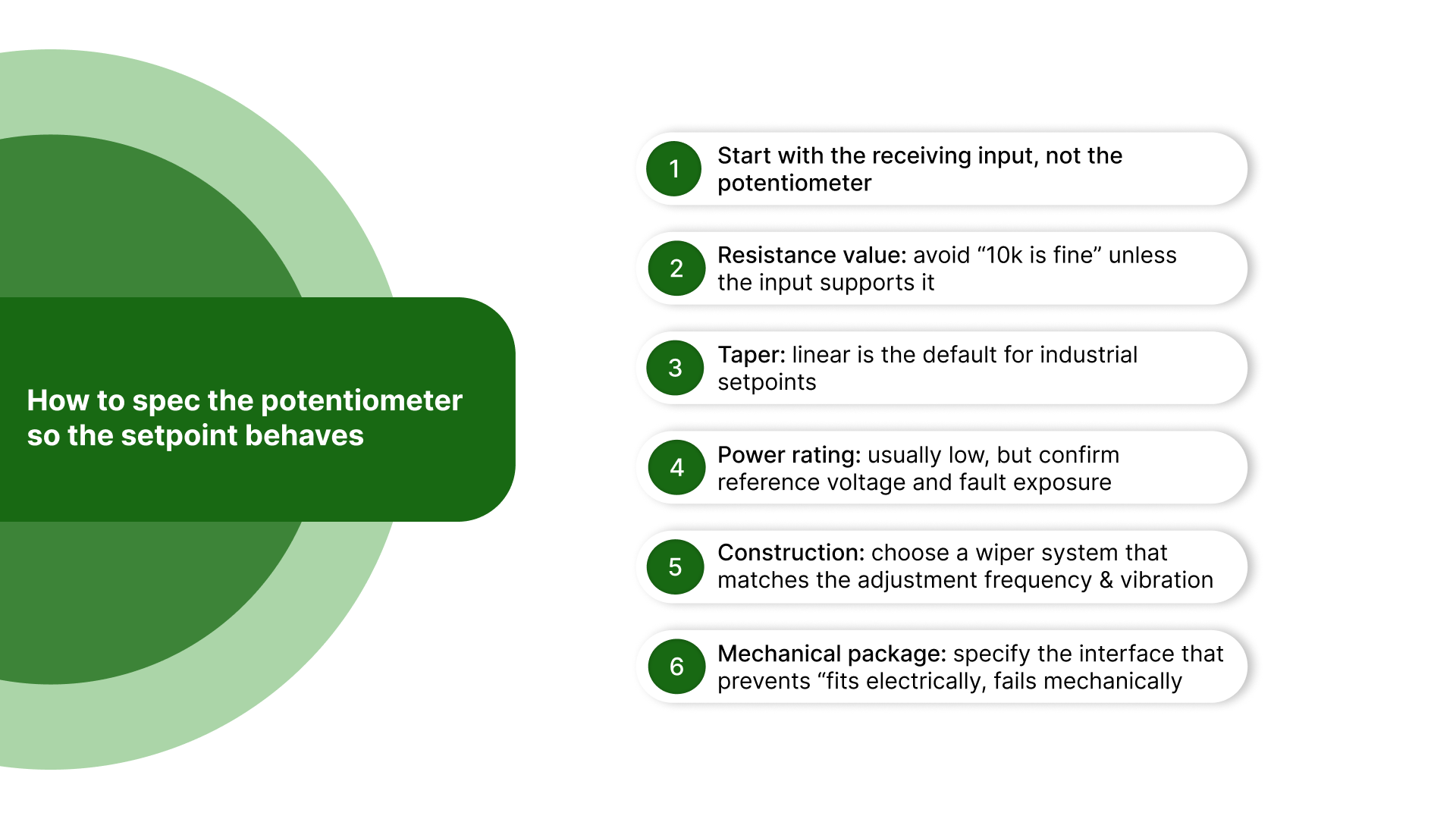
Start with the receiving input, not the potentiometer
Before you pick a value, confirm what the receiving device is designed to accept:
Does it provide a dedicated reference output (often labeled +10V / COM / AI)? If yes, it usually expects a potentiometer divider in a specific range.
What is the analog input type (0–10V, 1–10V, 4–20 mA, etc.) and input impedance (if published)?
Does the manual recommend a pot value range (e.g., “use 2k–10k”)?
If the manual gives a recommended value range, treat that as the default unless you have a reason to deviate.
Resistance value: avoid “10k is fine” unless the input supports it
The potentiometer’s resistance determines the source impedance feeding the analog input. If that source impedance is too high for the input (or the wiring environment), you’ll see classic symptoms: compressed range, jitter, and sensitivity to noise.
Use these practical rules:
Follow the drive/PLC recommendation first. Many devices are designed around a typical pot range and behave best there.
Lower resistance generally improves noise immunity (lower source impedance), but increases reference loading (more current drawn from the reference output).
Higher resistance reduces reference loading but can make the wiper signal more noise-sensitive and more affected by contact variation.
A safe way to state it in the article without over-math:
Choose a value that the receiving device expects. If no guidance exists, don’t assume. Confirm input impedance and reference capability first, then select a value that avoids a “soft” (high-impedance) wiper signal in a noisy cabinet.
Taper: linear is the default for industrial setpoints
For most control setpoints, you want a proportional relationship between knob position and voltage:
Linear taper is the standard choice for 0–10V / 1–10V setpoints.
Non-linear (log/audio) taper is only justified when:
the receiving device explicitly expects it, or
The process intentionally requires a non-linear response across travel.
If operators report “all the change happens at one end,” don’t automatically blame wiring—check:
taper type,
input scaling/parameters, and
whether the resistance range is appropriate for the receiving input.
Power rating: usually low, but confirm reference voltage and fault exposure
Setpoint pots typically dissipate very little power because they feed a high-impedance input. Still, confirm two things:
Reference voltage level actually present at the terminals (10V reference vs 24V control power mistakenly used as reference).
Fault exposure: what happens if the wiper lead shorts, opens, or is mis-landed? (This is less about continuous power and more about not selecting a part that fails immediately under predictable wiring faults.)
Construction: choose a wiper system that matches the adjustment frequency and vibration
“Construction” is where many “it worked for a month” installs fail. For panel setpoints, focus on stability and contact reliability:
Wiper/contact quality: higher-quality wiper systems reduce intermittent behavior, micro-dropouts, and drift.
Element type considerations (practical, not academic):
Choose constructions intended for signal/setpoint duty, not light hobby-grade controls
If the environment is vibration-prone or the setpoint is adjusted frequently, prioritize robust wiper design and long-life constructions
Environmental fit: if there’s dust, oil mist, washdown, or condensation risk, specify sealed or protected constructions appropriate to the enclosure.
Mechanical package: specify the interface that prevents “fits electrically, fails mechanically.”
You’re not doing mounting steps here, but you should lock the mechanical spec so the part is actually usable in the panel:
Bushing type/thread and panel thickness compatibility
Shaft diameter/length and knob interface (D-flat/keyed/set-screw expectation)
Terminal style/orientation that suits the wiring space (so wiring isn’t forced into stress or tight bends)
Even a correctly specified potentiometer will behave poorly if wiring and routing are sloppy, so the next step is wiring discipline that protects reference integrity and keeps the wiper signal quiet.
Wire and route it for stability
A setpoint potentiometer is a low-level signal source. If the wiper lead is routed like general control wiring, the typical outcomes are predictable: jitter when switching loads operate, random jumps, or a setpoint that changes once the door is closed and wiring is dressed.
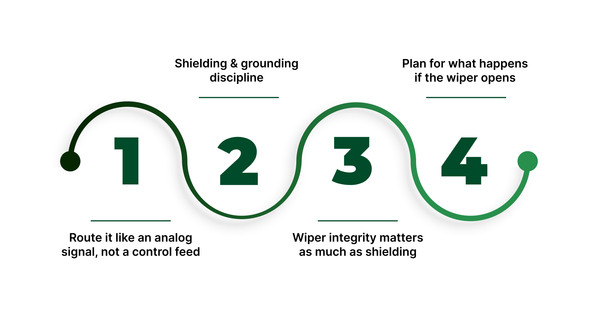
Route it like an analog signal, not a control feed
Keep the setpoint run separated from motor leads/VFD outputs and other high-switching bundles (contactors, coil wiring, transformer primaries).
Avoid long parallel runs next to noisy conductors; cross at 90° when you must intersect.
Keep the signal + reference return together as a pair so they share the same noise environment.
Shielding and grounding discipline
Use shielded cable when the panel has drives, frequent switching, or long setpoint runs.
Terminate the shield per your site practice (commonly one end only to reduce loop risk).
Maintain a clean reference low/COM path for the setpoint; do not “borrow” high-current returns.
Wiper integrity matters as much as shielding
Loose screws, weak crimps, or unsupported conductors can behave like “noise” by creating micro-open events.
Add strain relief at the pot and at the receiving terminals so door motion and vibration cannot tug on the wiper connection.
Plan for what happens if the wiper opens
Depending on the input design, an open wiper can drive the signal toward an extreme or create unstable readings.
Where the process risk is meaningful, choose a wiring/input approach that biases toward the safer default state (per the receiving device’s documented behavior).
With routing and terminations handled, the next step is a short decision checklist to confirm whether you need a different interface method, a different pot specification, or simply a cleaner signal path.
Decision checklist before you buy or rework anything
Before you order a “24V potentiometer” or start moving wires, pause and run these minimum checks. The goal is to confirm what the receiving device actually expects and why the current behavior is failing, so you don’t “fix” the wrong problem.
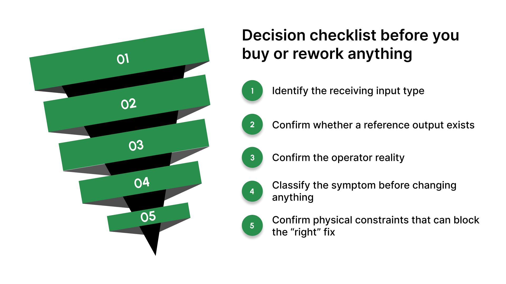
Identify the receiving input type (don’t assume).
At the receiving terminals (drive/PLC/controller), confirm whether the setpoint input is 0–10 V / 1–10 V, 4–20 mA, or digital/comms/internal reference. Use terminal labels, I/O card identification, or the device manual wiring example.
Confirm whether a reference output exists.
Look specifically for a dedicated +10 V / Vref and COM/0V near the analog input.
If it exists, it typically defines the correct setpoint method—use the provided reference, not 24V control power.
Confirm the operator reality (this drives the hardware choice).
Who adjusts the setpoint, how often, and under what access constraints?
If access is restricted or repeatability matters, a simple knob may not be the right interface—this is where motorized setpoints or a dedicated setpoint source becomes the correct choice.
Classify the symptom before changing anything.
Put the issue in one bucket, each point to a different root cause:
Compressed range: won’t hit true min/max at the receiving input
Noise/jitter: value moves when contactors/drives/motors switch
Drift after install: stable on the bench, unstable once wiring is dressed/door closed
Confirm physical constraints that can block the “right” fix.
Check the routing path and panel layout: separation from high-noise conductors, ability to run shielded cable if needed, and whether you can land a clean reference return without sharing high-current paths.
What you should have at the end: a clear statement of input type + reference availability + access requirement + symptom category.
If any one of those is unclear, buying parts or re-terminating wiring is usually premature.
Get the Setpoint Right at the Receiving Terminals
If the checklist points to a mismatch—compressed range, jitter when equipment switches, or a setpoint that changes once wiring is dressed—the fastest fix is usually not “a different potentiometer.” It’s confirming what the receiving device is actually designed to read, and then choosing the simplest setpoint method that will remain stable in the cabinet.
On Line Controls can help you close that gap, starting from what’s in front of you in the panel:
Confirm the intended setpoint interface at the receiving terminals (reference-divider input, conditioned voltage input, 4–20 mA input, or a non-analog setpoint path), so you are not forcing a 24V wiper into a terminal that was never meant to see it.
Align the electrical behavior to the input so the setpoint uses the full usable range and remains stable (correct value/taper when a potentiometer is appropriate, or the correct interface device when 24V is the only control power).
Match the mechanical package to the installation reality so it mounts cleanly and stays serviceable (shaft/bushing format, mounting hardware, terminal orientation, clearance, and practical access).
Offer a better path when the real requirement is access control or repeatability (guarded adjustment, motorized/remote adjustment, or a dedicated setpoint source that won’t drift or get “bumped”).
If you’re not 100% sure the receiving input is being fed the way it was designed to be fed, loop in On Line Controls before you rewire. A quick look at the terminal labels and your setpoint requirement is usually enough to confirm the correct approach.
Conclusion
A “24V DC potentiometer” request is usually shorthand not a wiring instruction. In most cabinets, 24V is control power, while the receiving device expects a specific setpoint method: a 0–10V divider off a reference output, a conditioned voltage/current signal, or a digital/internal setpoint.
If you identify the receiving input first and match the setpoint method to what it was designed to accept, the setpoint becomes predictable: full usable range, stable behavior under switching noise, and consistent performance after the panel is dressed and closed.
FAQs
Can I wire a potentiometer directly to 24V to get a variable voltage output?
Electrically, yes, you can generate a 0–24V wiper. Practically, that does not mean the receiving input is rated for it or will scale it correctly. Many analog inputs are designed around 0–10V or 4–20 mA, so a raw 24V wiper often creates range, stability, or input-rating problems.
Why does my “24V pot” only work over part of the knob travel?
Most often, it’s input loading, scaling, or taper/value mismatch. The receiving input may compress the effective range, or the pot’s value/taper doesn’t match what the device expects for a divider-style setpoint.
What should I use if my drive input is 4–20 mA?
Use a proper 4–20 mA source (transmitter, signal conditioner, or PLC analog output). A potentiometer by itself is a voltage divider, not a current source—unless it’s part of a purpose-built transmitter/interface.
How do I know if the drive provides a 10V reference for a potentiometer?
Look for terminals labeled +10V (or Vref) and COM/0V near the analog input terminal (AI). If you’re unsure, the fastest confirmation is the wiring diagram in the drive manual under “analog speed reference” or “external setpoint.”
When should I use a motorized potentiometer instead of a manual knob?
When the setpoint must be adjusted without opening a guarded enclosure, when you need repeatability across changeovers, or when access control matters (preventing bump/tamper). Motorized setpoints make sense when the “knob” has become an operational risk.
What causes setpoint jitter when motors or contactors switch?
Common causes are routing setpoint wiring near high-noise conductors, inconsistent reference return practices, or marginal terminations at the wiper/input that behave like intermittents. It’s usually a wiring/routing/reference integrity issue, not a “bad potentiometer” first.