DC Motor Speed Control for Retrofits: Rheostat vs PWM vs Setpoint Knob - Google Drive
A variable resistor on a DC motor is one of those ideas that refuses to die because sometimes it works exactly as intended. You need a coarse limiter. A simple trim. A quick way to knock the top end down without redesigning the circuit.
The catch is that the same knob can behave like a “speed control” on the bench and like a heat load in the field.
The difference is the motor type, the load, and how much power the resistor has to absorb once the work starts.
In this guide, you’ll get a fast way to decide if a variable resistor is a valid tool for your DC motor, what type and rating to choose if it is, and what to use instead when you need speed you can set and repeat.
Key Takeaways
Can I use a variable resistor on a DC motor? Yes, in some brushed DC/PMDC cases, but it’s load-dependent, and the resistor will dissipate heat by design.
What type should I use? Use a rheostat-style, 2-terminal series variable resistor for true load-path resistance; use a potentiometer only when it’s meant to set a control input/setpoint.
What rating should I use? Pick by wattage + duty cycle + enclosure heat/airflow first, then choose an ohms range that gives usable adjustment across the knob travel.
What’s the better option? For repeatable speed and efficiency, use a PWM DC speed controller (or a controller that accepts a pot/setpoint input).
First, identify the DC motor you actually have
Before you pick a variable resistor, identify the motor type and the outcome you’re trying to control.
That one step determines whether series resistance is even a reasonable approach, and what kind of behavior you should expect once the load changes.
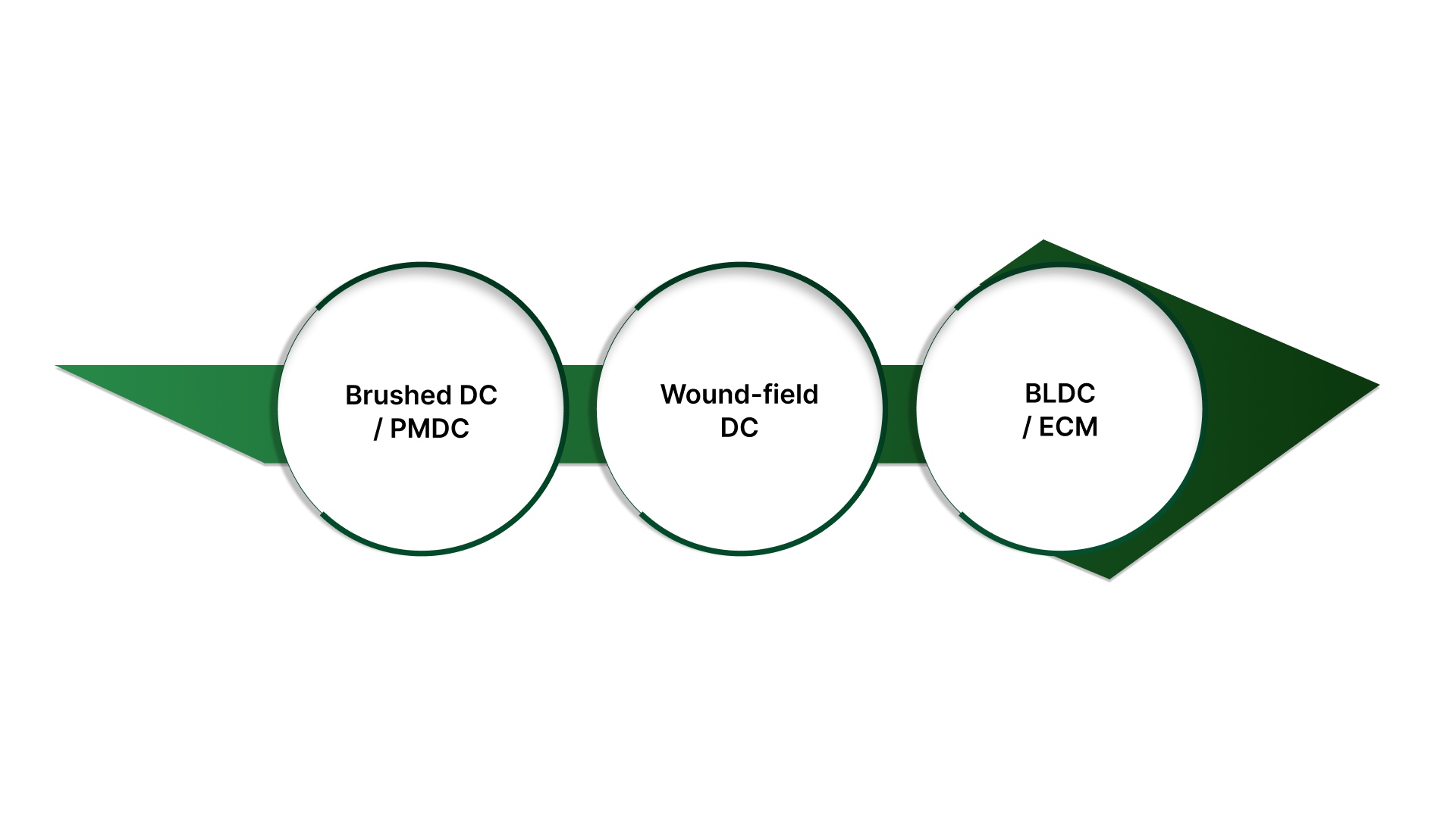
Brushed DC / PMDC (permanent magnet DC)
The most common case is where a variable resistor is considered.
Series resistance can reduce speed under load, but torque drops as the work increases; therefore, the resistor must be sized to handle the resulting heat.
Wound-field DC (series or shunt field)
These motors don’t behave like PMDC. Speed/torque response depends on the field, so a “drop voltage with resistance” approach can be less predictable than people expect.
BLDC / ECM (electronically commutated)
These are designed to be controlled through electronics. Adding resistance in the power path typically won’t produce stable control and can lead to nuisance behavior.
Use the intended controller input or drive method instead.
Before you choose a method, decide what you actually need:
Coarse limiting / “cap the top end” can sometimes be acceptable with resistance (when properly rated).
Repeatable speed you can set and hold usually calls for a controller approach, not a resistor.
Quick note: Here we’re talking about resistance in the motor power path, not a small pot used as a controller input.
Fast decision table: Resistor vs PWM vs “pot as a control input.”
Use this as the quick filter. It separates “this will kind of work” from “this will hold speed” and “this is the wrong part in the wrong place.”
Option | What it changes | What you get in practice | Best fit |
|---|---|---|---|
Series variable resistor (rheostat use) | Adds series resistance, so the motor sees less voltage under load | Coarse reduction and load-dependent speed; torque drops as load rises; the resistor runs hot by design; it behaves best on light or steady loads | Simple limiting/trim on brushed DC/PMDC, where inefficiency is acceptable, and heat is managed |
PWM DC speed controller | Controls average motor voltage electronically (efficiently) | More stable speed under changing load, better torque retention, far less wasted heat | Most cases where you need repeatable speed or any kind of efficiency |
Potentiometer as controller setpoint (not in the power path) | Adjusts a controller/drive input (signal level) | “Knob control” with repeatable behavior because the controller does the power handling; no significant power dissipation in the pot | When the system already has (or can accept) a controller that takes a pot/setpoint input |
Most people ask for a variable resistor, and mean the first row. In practice, many applications actually need PWM control or a pot used as a setpoint into a controller to get stable, repeatable results.
How a series variable resistor changes a DC motor
A series variable resistor is a variable resistor used in a two-terminal role (the wiper plus one end of the resistive element), so turning the knob changes the resistance seen by the circuit.
In this arrangement, the variable resistor sits in series with the motor, which means the motor current has to pass through it. You’re not commanding speed the way a controller does. You’re creating an adjustable voltage drop in the power path.
What changes in practice:
The motor has less available voltage under load because some of the supply is dropped across the resistor.
As the load increases, the current rises, the voltage drop tends to increase, and the motor loses torque sooner than it would without the series resistance.
Speed becomes more sensitive to load changes because the “drop” isn’t fixed; it’s tied to how hard the motor is working.
The simple rule to remember: if the load changes, the speed won’t stay put with series resistance.
The sizing reality: why “it matched the ohms” still fails
Most “variable resistor on a DC motor” failures aren’t wiring problems. They’re heat problems. A series resistor reduces what the motor sees by dropping voltage, and the “missing” power doesn’t vanish. It’s converted into heat in the resistor.
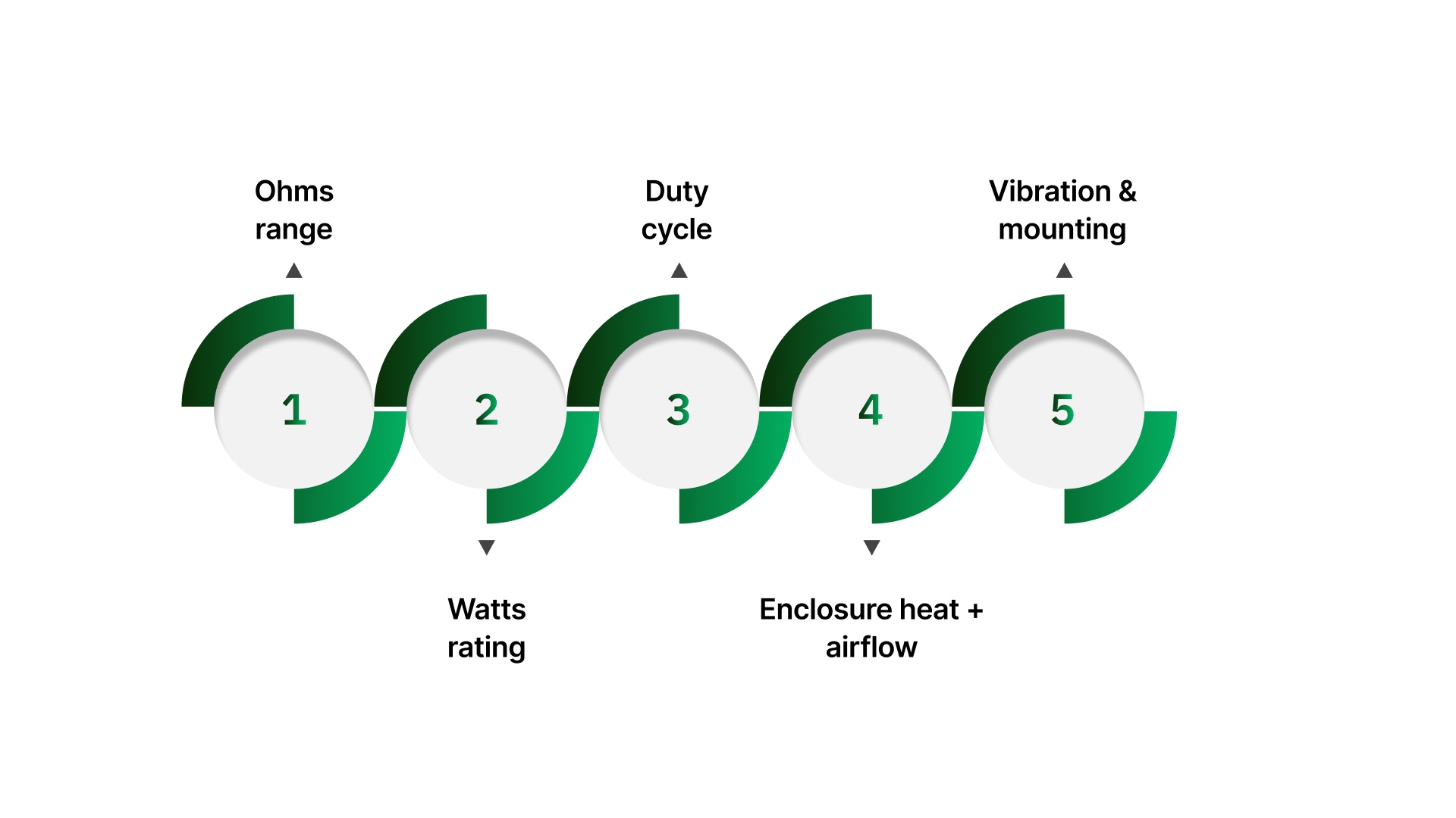
Here’s what you actually need to confirm:
Ohms range (usable adjustment)
You want a range that gives smooth control across the knob travel. If all the action is crammed into the last 10% of rotation, the value range is wrong for the job.
Watts rating (thermal margin)
This is the make-or-break spec. If the resistor is carrying real motor current, it will dissipate power continuously. Choose a rating that isn’t living on the edge in normal operation.
Duty cycle (setup-only vs continuous)
A resistor that survives for short setup trims may fail fast if it’s expected to sit under load all day. Continuous duty needs much more margin.
Enclosure heat + airflow
A part that “works on the bench” can cook inside a warm panel. High ambient temperature and poor airflow erase thermal headroom quickly.
Vibration and mounting
Movement and vibration accelerate wear and can create intermittent contact or drift over time. Make sure the mechanical mounting is stable and suited to the environment.
Practical takeaway: If the part is expected to run warm as part of normal operation, you’re already consuming thermal margin.
Move up in wattage (and improve heat dissipation), or use a control method that doesn’t dump excess power into a resistor.
Troubleshooting table: what you see vs what it usually means
When a resistor-based setup isn’t behaving, the symptoms are usually predictable—and they point to the same few root causes.
Symptom | Likely cause | First check |
|---|---|---|
It’s basically off / full speed | The wrong approach for the motor/load, or the resistance range, is poorly matched | Confirm motor type (brushed DC vs other) and whether the resistor is actually in the power path; sanity-check the ohms range |
The Series resistor/rheostat gets hot fast | Under-rated wattage, too much current, poor enclosure heat conditions | Check the watt rating vs expected use, duty cycle, and airflow/ambient temperature in the panel |
Won’t hold a steady speed | Normal behavior for series resistance under changing load | Verify whether the load varies; if speed must be repeatable, switch to PWM control |
Weak torque/stalls | Too much voltage drop under load, starving the motor of torque | Reduce series drop (if possible) or move to a controller that maintains torque better |
Works at idle, fails under load | Heat and voltage drop show up only when the current rises | Test/observe behavior at working load conditions; reassess wattage margin and method choice |
Use this map to decide whether you need a bigger thermal margin, a better match on resistance, or a different control method entirely.
Better ways to control DC motor speed (what most teams use)
If you need speed, you can set, document, and repeat. The usual fix is to stop “burning off” power in a resistor and use a control method designed to regulate motor power.
PWM DC speed controller (brushed DC / PMDC)
PWM control is the standard upgrade for stable DC speed control. It’s far more efficient than series resistance and typically maintains usable torque better as the load changes.
Controller + potentiometer input (when you still want a knob)
If the team wants a familiar dial, the clean approach is a controller that accepts a pot/setpoint input. The potentiometer becomes a low-power signal device, while the controller handles the motor current and does the “heavy lifting” cleanly and repeatably.
Quick note on wound-field DC motors
Field and armature control are different levers than “add resistance in series.” If you’re dealing with a wound-field motor, use the control method intended for that motor type rather than assuming PMDC behavior.
If you’re documenting a standard setting, planning changeovers, or troubleshooting recurring variation, a controller-based approach gives you a setting you can actually reproduce.
When motorized adjustment actually makes sense
Motorizing an adjustment is worth considering when the method itself is already valid, and the real pain is how the setting is applied day to day.
In other words, you’re not trying to turn a resistor into a real speed controller; you’re trying to make an intentional, resistive adjustment consistent and accessible.
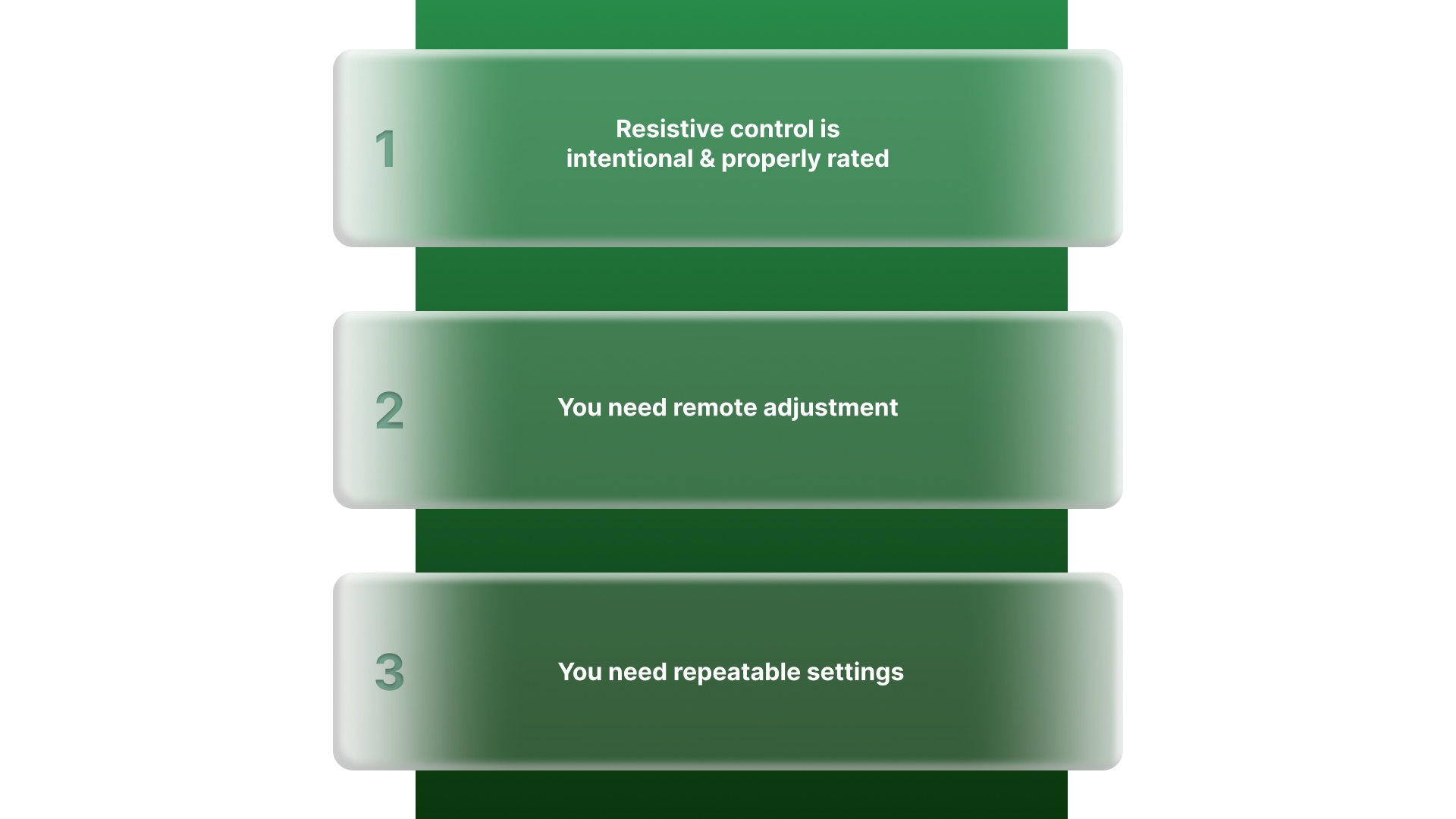
Resistive control is intentional and properly rated
This shows up in legacy circuits, test setups, current limiting, or “cap the top end” use cases where series resistance is part of the design and the resistor is sized for the heat it will dissipate.
You need remote adjustment
Useful when the knob lives inside a closed panel, behind guarding, or in an enclosure where opening the door is slow, unsafe, or disruptive.
You need repeatable settings
Helps when you want the same adjustment every time for changeovers, recipes, trials, or standardized setups without relying on feel or operator judgment.
Motorizing the adjustment doesn’t reduce heat load.
The solution only works when the rheostat is correctly rated for the watts, duty cycle, and enclosure conditions, which is why selection and build quality matter in retrofits.
Where On Line Controls fits in real DC retrofits
Once you’ve picked the right approach, the remaining challenge is usually practical: matching the part to a real panel and a real load, not just matching a number on paper.
That’s where On Line Controls fits, because their product line lines up with the same three paths in the decision table.
What On Line Controls provides
Motorized rheostats
Built for applications where series resistance in the load path is intentional, and the component has to handle real current and heat. This is the “series variable resistor” lane done with proper ratings and industrial construction.
Motorized potentiometers (MotorPots)
Designed for automating setpoints and control signals when the “knob” is really a low-power adjustment into a controller. This is often the cleaner retrofit when you want a dial but don’t want the dial dissipating power.
What this solves in the field

Legacy replacements that need a real match
Getting resistance right is only part of it. You also have to match wattage, duty cycle expectations, motor type/application intent, and mechanical mounting so the retrofit survives.
Repeatable settings with less operator variation
Motorized adjustment helps you return to the same setpoint for changeovers, trials, or standardized runs without “close enough” knob feel.
Remote control without redesigning the whole panel
If the adjustment point is inside a closed or guarded enclosure, motorized units let you move the control point without rebuilding the machine logic.
Next step: check the Motorized Rheostat and MotorPot product pages to narrow the closest fit.
If you’re replacing an existing unit, send the ohms, watts, duty cycle, motor type, and a photo/part number for the fastest match. Get in Touch!
Conclusion
A “variable resistor for a DC motor” can be a valid tool, but only when you treat it as what it is: series resistance with a heat load.
If the goal is a simple limit or a coarse trim on a brushed DC/PMDC setup, it can work provided the ohms range is usable, and the wattage/duty cycle match real operating conditions.
If the goal is repeatable speed, the smarter path is a controller-based method: PWM for DC speed control or a controller with a potentiometer input when you still want a knob.
And when the adjustment needs to be remote or consistent across shifts, motorized rheostats and MotorPots give you a practical retrofit route without rebuilding the entire panel.
FAQs
Can a variable resistor control DC motor speed?
Sometimes. It can reduce speed on certain brushed DC/PMDC motors by adding series resistance, but speed will still vary with load, and the resistor must be sized to handle the heat.
Why does a variable resistor get hot on a motor?
Because it’s burning off power as heat. Any voltage you “drop” across the resistor under motor current turns into heat in the resistor body.
What wattage rheostat do I need for a DC motor?
One that can dissipate the expected heat with a margin for duty cycle and enclosure temperature. If the application requires continuous operation and you expect it to run warm, step up in wattage or move to PWM control.
Can I use a potentiometer to control a DC motor directly?
Not directly in the power path for anything beyond very small currents. A potentiometer is typically used as a low-power signal input to a controller, not as the part carrying motor current.
What should I use instead of a resistor for DC motor speed control?
For brushed DC/PMDC motors, use a PWM DC speed controller. If you still want a knob, use a controller that accepts a potentiometer/setpoint input so the controller handles the motor power.