Instability in DC motor position control systems is rarely caused by insufficient motor torque or controller failure. In most industrial and legacy systems, the root cause is degraded or improperly managed position feedback.
When a potentiometer is used as the primary position sensor, the control loop becomes highly sensitive to mechanical play, electrical noise, signal resolution, and long-term component wear. If these factors are not addressed explicitly, the system will oscillate, drift, or continuously hunt around the target position.
In this guide, you will learn how DC motor position control with potentiometer feedback actually behaves in real industrial environments, why instability develops over time, and what engineering methods are required to achieve stability.
Key Takeaways
Mechanical integrity is important: Eliminate backlash and ensure rigid coupling to prevent oscillation and maintain accurate motor position.
Signal conditioning stabilizes feedback: Filter electrical noise and stabilize potentiometer voltage to avoid false error signals and hunting.
Deadband reduces overcorrection: Introduce a tolerance range around the setpoint to suppress micro-adjustments caused by minor voltage fluctuations.
Control gain must match system dynamics: Tune proportional, integral, and derivative gains to prevent overshoot and ensure smooth motor response.
Manage thermal and wear-induced drift: Select low-drift, durable potentiometers to preserve long-term loop stability and prevent slow positional errors.
How Does DC Motor Position Control with Potentiometer Feedback Work?
A potentiometer-based DC motor position control system is a closed-loop analog feedback system. The controller does not “know” where the motor is physically located. It only reacts to voltage differences.
The system consists of four core elements:
A reference signal representing the desired position
A controller that compares reference and feedback voltages
A DC motor and drive stage that moves until the error is reduced
A feedback potentiometer mechanically linked to the motor or driven load
The potentiometer converts angular position into a proportional voltage, typically across a fixed resistance track. As the motor rotates, the wiper position changes, producing a voltage that represents the shaft position. The controller continuously calculates the difference between the reference voltage and the feedback voltage. This difference, known as the error signal, determines motor direction and speed.
The system is considered stable only when the motor reaches the commanded position and remains there without continuous correction.
At its core, stability depends entirely on how accurately and consistently the potentiometer converts mechanical position into a usable electrical signal. Any disturbance in this conversion directly affects control behavior.
To understand why instability occurs, it is necessary to learn how this feedback signal degrades under real operating conditions.
Why Potentiometer-Based Position Control Becomes Unstable?
Potentiometers are popular for position feedback due to their simplicity and low cost, but they add challenges that can undermine system stability. Even well-designed control loops may exhibit unexpected oscillation or drift when potentiometer feedback is used.
The following points break down the key reasons why potentiometer-based systems are especially prone to instability.
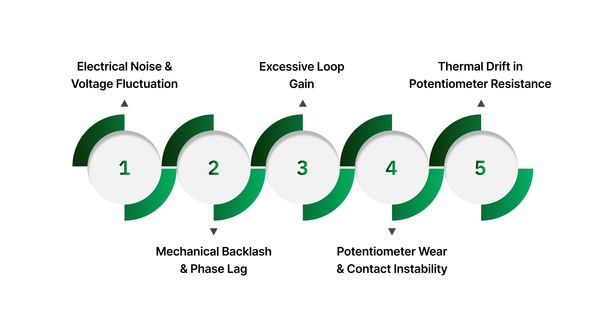
1. Electrical Noise and Voltage Fluctuation
Potentiometers produce low-level analog voltages. These signals are inherently vulnerable to interference from DC motor commutation, PWM motor drives, nearby power cables, and grounding inconsistencies.
Even small voltage fluctuations can be misinterpreted as position changes. When the controller reacts to these false signals, the motor begins making unnecessary corrective movements. Over time, it manifests as audible chatter, constant micro-adjustments, or visible oscillation around the setpoint.
In digital systems, analog-to-digital conversion amplifies this issue. Quantization error and sample jitter further distort the perceived position.
2. Mechanical Backlash and Phase Lag
Potentiometers measure shaft position, not load position. Any mechanical compliance between the motor shaft and the potentiometer causes a delay.
Common sources include:
Worn bearings
Flexible couplings
Gearbox backlash
Shaft misalignment
When the direction changes, the potentiometer does not immediately reflect the actual movement of the load. The controller responds late, overshoots the target, and then corrects again in the opposite direction. It creates an oscillation that cannot be corrected through software tuning alone.
3. Excessive Loop Gain
High loop gain increases responsiveness but reduces stability margins. In potentiometer-based systems, delay and noise are unavoidable. Excessive proportional gain causes the controller to overreact to these imperfections, resulting in sustained oscillation or ringing.
Reducing gain improves stability but introduces steady-state error. This tradeoff must be managed deliberately.
4. Potentiometer Wear and Contact Instability
Most industrial potentiometers rely on mechanical contact between the wiper and the resistive element. Over time, this contact degrades.
Wear raises:
Increased contact noise
Localized voltage jumps
Resistance discontinuities
These effects are especially problematic in position-hold applications, where the motor remains stationary for long periods. The controller continues to see small voltage changes and attempts correction, even though the mechanical position has not changed.
5. Thermal Drift in the Potentiometer Resistance Track
Potentiometer resistance is temperature-dependent. As ambient or internal temperature changes, the resistance of the track shifts, causing the output voltage to change even when the mechanical position remains fixed. The controller interprets this voltage drift as a position error and commands corrective motor movement, leading to slow drift or continuous micro-adjustments.
This issue is most visible during long position-hold periods, in enclosures exposed to temperature cycling, and in industrial environments without active climate control.
A single factor rarely causes instability. It is the cumulative effect of electrical noise, mechanical delay, control gain, and sensor degradation.
Stabilizing the system requires addressing each of these factors at the feedback, mechanical, and control-loop levels.
How to Stabilize DC Motor Position Control with a Potentiometer?
Stabilizing DC motor position control with potentiometer feedback requires addressing instability at its source. In most systems, instability does not originate from the controller logic, but rather from the interaction between mechanical motion, analog feedback signals, and loop response timing.
The following methods target those failure mechanisms directly and, when applied together, produce a stable, repeatable position control system suitable for long-term industrial operation:
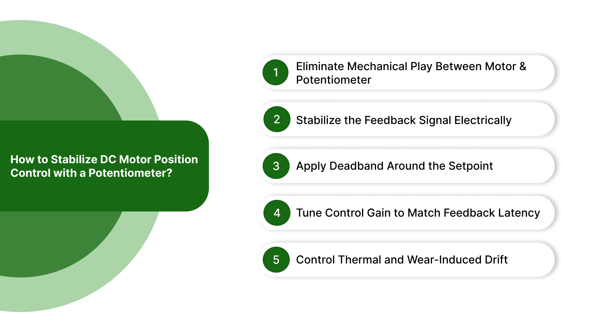
1. Eliminate Mechanical Play Between Motor and Potentiometer
Why it matters: Backlash or loose coupling causes phase lag, overshoot, and oscillation.
Steps to eliminate mechanical play:
Inspect all couplings between the motor and potentiometer for any looseness.
Replace flexible or worn couplings with rigid, precision couplings wherever possible.
Minimize intermediate gear stages between the motor shaft and the potentiometer shaft.
Ensure shaft alignment is tight and bearings are in good condition.
Test motor direction reversals to verify that the potentiometer shaft immediately reflects actual load movement.
Outcome: The feedback signal represents true motor position, eliminating oscillation caused by mechanical delay.
2. Stabilize the Feedback Signal Electrically
Why it matters: Noise in the potentiometer voltage creates false error signals, causing micro-corrections or hunting.
Steps to stabilize the signal:
Identify electrical noise sources (motor brushes, PWM drives, nearby high-current cables).
Implement proper grounding and shielding for potentiometer wiring.
Add a low-pass RC filter to attenuate high-frequency noise on the feedback voltage.
In digital systems, use averaging or moving-window filtering to smooth ADC readings.
Verify filtered feedback shows minimal jitter while still responding to real motion.
Outcome: The controller sees an accurate representation of position, not noise-induced artifacts, reducing unnecessary motor motion.
3. Apply Deadband Around the Setpoint
Why it matters: Feedback noise and minor drift can trigger continuous corrections if zero-error is treated as required.
Steps to implement deadband:
Determine acceptable voltage range around the setpoint based on resolution and system tolerance.
Configure the controller to ignore errors within this range.
Validate that small voltage fluctuations no longer cause corrective motor action.
Adjust deadband width carefully, as too narrow causes continued corrections, too wide reduces positioning accuracy.
Monitor the system over time to confirm that the deadband prevents hunting without introducing steady-state error.
Outcome: The system remains stable, holding position even in the presence of minor voltage fluctuations.
4. Tune Control Gain to Match Feedback Latency
Why it matters: Excessive gain causes overshoot and oscillation; insufficient gain slows response.
Steps for tuning gain:
Measure total feedback path delay, including mechanical inertia, coupling lag, and signal processing.
Set proportional gain so that the controller response matches system latency without overshoot.
Add derivative action if available to provide damping and reduce overshoot.
Limit integral gain to avoid slow oscillations caused by accumulated error.
Test with step input changes to confirm a smooth approach to the target position without oscillation.
Outcome: The motor moves quickly but stably to the target position, with no hunting or overshoot.
5. Control Thermal and Wear-Induced Drift
Why it matters: Temperature changes and potentiometer wear shift output voltage over time, creating false error signals.
Steps to control drift:
Select potentiometers with low thermal coefficient resistance for minimal voltage shift under temperature variation.
Use sealed, high-quality potentiometers to reduce mechanical wear.
Maintain the system environment to minimize rapid temperature cycling where possible.
Periodically inspect and recalibrate if operating in extreme conditions.
Monitor long-term drift trends to confirm that voltage changes remain within acceptable tolerance.
Outcome: The feedback signal remains accurate over long periods, preventing slow position creep or continuous micro-adjustments.
Stabilizing DC motor position control with potentiometer feedback requires coordinated mechanical, electrical, and control-loop interventions. No single adjustment is sufficient on its own. Stability emerges when feedback accurately reflects position, noise is suppressed, control response is properly damped, and long-term drift is minimized.
With stabilization mechanisms in place, the next step is ensuring that the potentiometer itself is suitable for sustained, stable operation. It makes component selection a critical factor in long-term system performance.
How to Select a Potentiometer for Stable Position Control?
Selecting the right potentiometer is essential to maintaining stable DC motor position control. Even a perfectly tuned system will oscillate or drift if the feedback sensor cannot provide accurate, repeatable, and durable voltage output.
The following criterias ensure the potentiometer supports long-term stability in industrial and legacy systems:
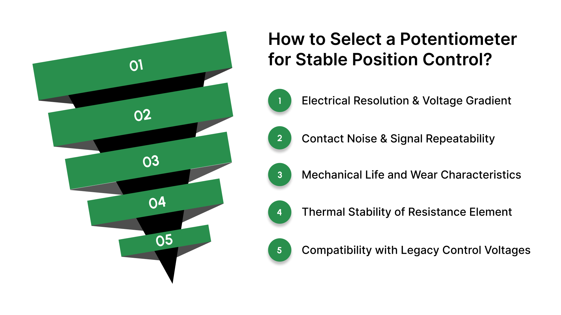
Electrical Resolution and Voltage Gradient: Choose a potentiometer that produces small voltage changes per degree of rotation. Higher resolution minimizes quantization effects and allows the controller to detect fine position deviations accurately.
Contact Noise and Signal Repeatability: Select a potentiometer with low contact resistance variation. Minimize voltage jitter caused by wiper fluctuations to prevent false error signals and unnecessary motor corrections.
Mechanical Life and Wear Characteristics: Use a potentiometer rated for high cycle counts with robust wiper and track materials. Long mechanical life maintains consistent voltage output and reduces maintenance and recalibration needs.
Thermal Stability of Resistance Element: Pick a potentiometer with a low temperature coefficient. Stable resistance under varying ambient or internal temperatures ensures voltage output does not drift, preserving loop stability.
Compatibility with Legacy Control Voltages: Confirm that the potentiometer matches the voltage range and input requirements of existing controllers. Exact compatibility prevents signal scaling errors and eliminates the need for additional signal conditioning.
A high-quality potentiometer is the foundation of stable position control. When resolution, contact reliability, mechanical life, thermal stability, and voltage compatibility are properly addressed, the control loop can operate as designed with minimal drift or oscillation.
With the correct potentiometer selected, the next step is applying these principles to real-world industrial setups, where exact-match components and legacy system considerations determine how stability is achieved in practice.
Eliminate Control Drift with OLC Motorized Potentiometers
On Line Controls is a US-based manufacturer specializing in precision motorized potentiometers and ultra-sensitive control components for industrial systems where accurate analog position feedback is critical to system stability.
OLC serves manufacturers and maintenance teams operating legacy or long-life DC motor control systems in industries where redesigning control architecture is impractical, risky, or cost-prohibitive.
In these environments, stability depends less on theoretical control tuning and more on restoring correct feedback behavior using components that match original system characteristics.
Exact-Match Motorized Potentiometers for Legacy Systems: OLC provides direct-replacement motorized potentiometers that match original electrical, mechanical, and mounting specifications, eliminating instability caused by retrofits or signal scaling mismatches in legacy control systems.
High-Resolution, Low-Noise Feedback: Our potentiometers deliver stable, repeatable voltage output with minimal contact noise, allowing controllers to resolve small position errors without inducing oscillation or unnecessary corrective motor movement.
Long-Life Mechanical Design: Designed for continuous industrial duty, OLC potentiometers maintain consistent resistance characteristics over long service life, preventing drift, dead spots, and recalibration cycles that destabilize position control loops.
Thermal Stability in Industrial Environments: We use resistance elements with low temperature coefficients, reducing thermal drift that can falsely appear as position error during long hold periods or temperature cycling.
Drop-In Integration with Existing Control Loops: Our components integrate smoothly into existing DC motor control architectures, preserving original loop dynamics while restoring stability, accuracy, and repeatability without firmware or hardware redesign.
By restoring accurate, stable feedback at the source, OLC enables engineers to stabilize DC motor position control systems while preserving existing control logic and mechanical design.
Conclusion
DC motor position control with potentiometer feedback can be stable, accurate, and durable when feedback integrity is treated as a primary engineering concern. Most instability problems are not caused by control theory limitations but by mechanical wear, electrical noise, and aging components.
Stability is achieved by designing for feedback quality, mechanical integrity, signal conditioning, and long-term reliability from the start.
Discuss your position control requirements with On Line Controls. Identify exact-match, long-life potentiometer solutions for legacy and industrial systems.
Frequently Asked Questions
1. What is DC motor position control with potentiometer feedback?
DC motor position control with potentiometer feedback uses a potentiometer mechanically linked to the motor or load shaft to generate a voltage proportional to angular position. A closed‑loop controller compares this feedback voltage to a reference signal and drives the motor until the error is reduced to zero. This method allows precise shaft positioning.
2. How does a potentiometer affect the stability of position control?
The potentiometer output directly affects stability because its analog voltage is the feedback signal. Noise, contact variation, temperature drift, or mechanical play cause the controller to interpret false position changes, resulting in oscillation or hunting. Stable operation requires clean, high‑resolution, low‑drift potentiometer feedback.
3. Can a potentiometer alone control DC motor position?
A potentiometer alone does not control motor position; it only senses position. Control stability depends on the interaction between the potentiometer feedback, the controller’s algorithm (e.g., PID), and the mechanical system. Without proper conditioning and tuning, potentiometer noise or drift leads to unstable positioning.
4. Why do DC motor position systems oscillate with potentiometer feedback?
Oscillation occurs when mechanical phase lag, electrical noise, or excessive loop gain cause the controller to overreact to small feedback changes. Backlash or coupling play introduces delay, while noise in the potentiometer signal gets interpreted as movement, leading to repeated corrective motion. Proper damping and filtering reduce this effect.
5. How is potentiometer resolution important for position control?
Higher potentiometer resolution produces finer voltage changes per degree of movement, allowing the controller to detect smaller position errors accurately. Low resolution creates coarse steps in feedback voltage, degrading loop stability and increasing steady‑state error or hunting. Good resolution directly improves control precision.