Introduction
A motorized potentiometer that starts drifting, stalling, or outputting erratic signals can bring an entire extrusion line to a halt — and the root cause isn't always obvious. These compact electromechanical assemblies pack a potentiometer element, gear reduction system, slip clutch, and motor into a single unit, which means problems can originate from several directions at once.
Failures typically trace back to four sources:
- Mechanical wear in gears and bearings
- Electrical degradation of the resistive track or wiper contacts
- Environmental contamination from dust and moisture
- Improper installation or operating parameters
Catching problems early — before signal noise or position drift becomes a full stop — is what separates a quick fix from a costly production shutdown. This guide walks through the 7 most common motorized potentiometer problems, what causes them, and how to resolve each one.
Key Takeaways
- Erratic resistance readings, motor failures, mechanical binding, and control signal issues represent the most common motorized potentiometer problems
- Diagnose systematically — test the potentiometer element and motor drive system independently before attempting repairs
- Most issues resolve cost-effectively by cleaning contaminated contacts, replacing worn gears, or recalibrating position feedback
- Replace over repair when multiple systems fail simultaneously or the unit is nearing its 10–20 year service life
What Is a Motorized Potentiometer?
A motorized potentiometer is a variable resistor coupled with a precision motor that enables automated position adjustment and remote control. This electromechanical assembly provides analog position feedback and motorized actuation in a single integrated unit.
The motor drives the potentiometer shaft through a gear reduction assembly that converts high motor speed into precise, controlled movement. Run-up and run-down times range from 10 to 300 seconds depending on the gearbox configuration.
A factory-calibrated slip clutch allows manual override when power is disconnected and prevents motor damage when the wiper reaches its travel limits.
Typical applications include:
- Adjusts screw pump speed, gear pump speed, and puller speed on extrusion lines
- Controls remote analog setpoints across process equipment
- Delivers absolute position data for actuators and valve positioning
- Trims governor speed and voltage output for generator power factor control
Units built with Japanese potentiometers and Swiss-made motors and geartrains routinely last 10–20+ years in industrial service. Understanding how these components work together also makes it easier to pinpoint what's gone wrong when problems appear.
Common Problems With Motorized Potentiometers
Most motorized potentiometer failures fall into recognizable patterns. Testing mechanical and electrical subsystems separately makes diagnosis faster and more accurate.
Problem 1: Erratic or Jumpy Resistance Readings
Symptoms: Inconsistent output voltage, signal noise visible on oscilloscope as vertical spikes, intermittent operation, or sudden jumps in resistance values during rotation.
Causes include:
- Dust mixed with old lubricant forms an abrasive paste between the wiper and resistive track
- Oxidation on the resistive element creates non-conductive spots
- Worn wiper contact loses spring tension, causing intermittent connection
- Continuous dithering around a single setpoint wears physical dead zones into the track
Problem 2: Motor Runs But Shaft Doesn't Move
Symptoms: Motor hums or operates normally with correct voltage and current draw, but no shaft rotation occurs. Manual rotation may feel loose or disconnected.
Causes include:
- Stripped gear teeth in the reduction assembly — torque can't transfer to the shaft
- Slip clutch worn beyond its load threshold, slipping under normal operating conditions
- Broken coupling between the motor shaft and potentiometer shaft
- Gear train damage from forced rotation beyond the mechanical stops
Problem 3: No Motor Response to Input Commands
Symptoms: Potentiometer works correctly when rotated manually with smooth resistance changes, but motor doesn't activate when control signals are applied.
Causes include:
- Open or shorted motor windings
- Broken wiring or loose terminal connections at the motor
- Failed driver circuit or control board components
- Wrong control voltage — incorrect DC level or AC supplied where DC is required
- Worn brushes losing electrical contact with the commutator
Problem 4: Motor Runs Continuously Without Stopping
Symptoms: Motor doesn't stop at commanded position, runs to mechanical limit stops, or oscillates continuously around setpoint.
Causes include:
- Lost position feedback signal from the potentiometer to the control system
- Control circuit failure blocking stop commands from reaching the motor
- Incorrect limit switch settings or a failed limit switch
- Reversed feedback wiring, causing the control loop to drive in the wrong direction
Problem 5: Resistance Value Doesn't Match Physical Position
Symptoms: Calibration drift where resistance values no longer correspond to expected positions. Zero-point error at one end of travel. Non-linear response through rotation range.
Causes include:
- Mechanical slippage between the motor output shaft and potentiometer input shaft
- Worn coupling components allowing rotational play
- Accumulated gear backlash in the reduction assembly
- Slip clutch engaging prematurely under normal operating torque
Problem 6: Mechanical Binding or Excessive Friction
Symptoms: Difficult manual rotation requiring excessive force. Motor stalls under normal load or draws excessive current. Grinding or scraping noises during operation. Uneven resistance to rotation through travel range.
Causes include:
- Environmental dust and debris contaminating the gear mechanism
- Bearing failure causing shaft misalignment
- Component misalignment from improper installation or physical impact
- Dried or degraded lubricant that now increases friction rather than reducing it
Problem 7: Intermittent Operation or Dead Spots
Symptoms: Unit works correctly in some shaft positions but fails in others. Complete loss of electrical continuity in specific rotation ranges. Resistance jumps to infinite or zero in certain positions.
Causes include:
- Damaged resistive track sections from excessive current, wear, or contamination
- Broken internal solder connections or failed terminal attachments
- Grooves worn into the resistive element where the wiper repeatedly contacts it
- Cracked resistive substrate from thermal cycling or mechanical stress
Why Motorized Potentiometers Fail
Failures stem from the dual nature of these devices—both mechanical components (motor, gears, bearings) and electrical elements (resistive track, wiper, terminals) experience stress that accumulates over time.
Repeated cycling through the full rotation range wears down the resistive track and motor brushes. High-speed adjustments increase gear tooth loading and bearing stress, while continuous duty cycles generate heat that breaks down lubricants and insulation. Field analysis identifies wiper contamination and oxidation as dominant electrical failure modes, with slip clutch wear and gear stripping as the leading mechanical failures.
Environmental exposure hits multiple subsystems at once. Common culprits include:
- Dust mixing with lubricants to form abrasive compounds that accelerate gear and track wear
- Moisture causing corrosion on terminals and oxidation on contact surfaces
- Temperature extremes outside the -20°C to +70°C operating range, leading to housing deformation and lubricant migration
- Chemical vapors attacking plastic gears or contaminating the resistive element

Improper installation and usage are equally damaging. Incorrect voltage burns motor windings or creates hot spots on the resistive element. Excessive shaft load damages bearings and causes misalignment. Forcing rotation beyond travel limits under power strips gear teeth, and missing or incorrect lubrication accelerates friction-related wear throughout.
Left unaddressed, early warning signs compound quickly. Minor contact noise becomes an intermittent open circuit. Small gear backlash becomes complete coupling failure. Slight brush wear turns into commutator damage and motor burnout.
In extrusion applications specifically, these failures cause process control instability, product quality problems, and unplanned downtime—costs that far exceed what timely maintenance or a replacement unit would have required.
How to Fix a Motorized Potentiometer (Step-by-Step)
Before touching any components, determine where the fault actually lives — mechanical drivetrain, potentiometer element, motor, or control circuitry. Isolating the source first prevents unnecessary part replacement and gets you to the real fix faster.
Step 1: Identify the Exact Problem
Physical inspection and symptom documentation:
- Disconnect all power before handling the unit
- Manually rotate the shaft through its full range, noting any binding, excessive play, or rough spots
- Listen for grinding, clicking, or scraping sounds during manual rotation
- Inspect housing for cracks, loose fasteners, or signs of overheating
- Check all wiring connections for corrosion, loose terminals, or damaged insulation
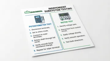
Independent potentiometer testing:
- Disconnect the potentiometer terminals from the control circuit
- Set a multimeter to resistance (ohms) mode
- Connect meter leads across the outer two terminals (full resistance)
- Slowly rotate the shaft manually through full travel
- Resistance should change smoothly and linearly without jumps or infinite readings
- Repeat measurement between wiper terminal and each outer terminal
Independent motor testing:
- Identify motor voltage specification (6V, 12V, or 24V DC for DC models; 115V AC for AC models)
- Disconnect motor from control circuit
- Apply appropriate voltage directly to motor terminals using a bench power supply
- Motor should run smoothly without excessive noise or vibration
- For DC motors, verify operation in both directions by reversing polarity
Problem pattern documentation:
- Note whether failure is constant or occurs only under specific conditions
- Record if issues are position-dependent (certain rotation angles only)
- Document environmental factors (temperature, humidity, vibration)
- Track frequency of occurrence and any triggering events
Step 2: Confirm the Root Cause Category
Mechanical issues are indicated by:
- Physical inspection revealing stripped gear teeth, broken components, or excessive shaft play
- Motor runs normally but shaft doesn't rotate or rotates inconsistently
- Grinding noises or binding that prevents smooth manual rotation
- Visible misalignment between motor shaft and potentiometer shaft
Electrical issues (potentiometer element) are indicated by:
- Resistance measurements showing erratic jumps, open circuits, or readings outside specifications
- Infinite resistance readings in certain positions
- Resistance values that don't change smoothly during rotation
- Total resistance across outer terminals doesn't match rated value (within ±10%)
Electrical issues (motor) are indicated by:
- Motor doesn't run when correct voltage is applied directly to terminals
- Motor winding resistance measurements show open circuits (infinite resistance) or short circuits (near-zero resistance)
- Excessive current draw indicating shorted windings or bearing seizure
- Visible brush wear, commutator damage, or arcing during operation
Control/signal issues are indicated by:
- Both motor and potentiometer test correctly when isolated
- System doesn't respond to control inputs despite proper power supply
- Position feedback doesn't match actual shaft position
- Control signals present at input but motor doesn't activate
External factors to rule out:
- Verify power supply voltage under load matches specifications
- Check power supply current capacity exceeds motor requirements
- Test control signal integrity with oscilloscope or multimeter
- Inspect all wiring for breaks, shorts, or high-resistance connections
- Verify correct polarity on DC connections
Step 3: Fix Based on the Identified Problem
Once you've confirmed the root cause from Step 2, apply the corresponding repair below. Have the correct replacement parts and manufacturer documentation on hand before disassembling anything.
If the Problem Is Mechanical (Gears/Coupling)
Common mechanical failures:
- Plastic gear teeth strip under overload or repeated end-of-travel impacts
- Slip clutch mechanism wears, causing premature slippage under normal torque
- Shaft coupling cracks or loosens — often from sustained vibration or axial misalignment
- Gear lubrication dries out, creating excessive friction and accelerating wear
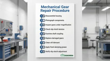
Repair procedure:
- Disassemble housing following manufacturer documentation (if available)
- Photograph component positions before disassembly for reference during reassembly
- Inspect all gears under magnification for tooth damage, cracks, or excessive wear
- Check slip clutch for proper spring tension and friction surface condition
- Examine shaft coupling for cracks, looseness, or wear
- Replace damaged gears with exact manufacturer replacements (gear pitch and tooth count must match precisely)
- Clean old lubricant from gear surfaces using appropriate solvent
- Apply fresh damping grease compatible with plastic gears (verify manufacturer recommendation)
- Verify slip clutch adjustment matches factory specification
Pre-reassembly verification:
- Manually rotate the assembly through full range—motion should be smooth without binding
- Check for excessive play in shaft bearings
- Confirm proper gear mesh with no tight spots or gaps
- Verify slip clutch engages at appropriate torque level
If the Problem Is Electrical (Potentiometer Element)
Common failure points:
- Resistive track wear from continuous operation at the same position
- Wiper contact contamination from environmental dust or degraded lubricant
- Loss of wiper spring tension reducing contact pressure
- Broken terminal connections from vibration or thermal cycling
- Physical track damage from excessive current
Cleaning and inspection procedure:
- Use electronics-grade contact cleaner (DeoxIT D5 works well) applied to the resistive element and wiper contact area
- Rotate the shaft repeatedly through full travel to work cleaner into contact surfaces
- Allow cleaner to evaporate completely (typically 5–10 minutes)
- Inspect resistive track under magnification for physical damage, cracks, or worn-through areas
- Check all terminal connections for cold solder joints or broken wires
- Measure resistance values and compare to manufacturer specifications (typically ±10% tolerance)
- Confirm readings are stable throughout the full rotation range before proceeding
Critical lubrication step:
Contact cleaners remove protective lubricants. You must re-lubricate to prevent rapid wear:
- Apply damping grease specifically designed for potentiometers (such as Rheolube 716A or similar)
- Use minimal quantity—excess grease attracts contamination
- Distribute grease evenly by rotating shaft through several complete cycles
- Verify smooth operation with appropriate tactile feedback
When cleaning isn't sufficient:
If resistive track shows physical damage (worn-through spots, cracks, or burns) or measurements remain erratic after thorough cleaning, the potentiometer element requires replacement. Attempting to use a damaged element will result in continued unreliable operation.
If the Problem Is Electrical (Motor)
Common motor failures:
- Carbon brush wear reduces contact with commutator, decreasing torque and causing intermittent operation
- Winding failures from thermal stress or mechanical damage cause complete motor failure
- Winding shorts reduce efficiency and cause overheating
- Commutator contamination from brush debris causes arcing and power loss
Inspection and testing:
- Measure motor winding resistance between terminals and compare to specifications (should be within ±10%)
- For DC motors, typical winding resistance ranges from 5–50 ohms depending on voltage rating
- Inspect carbon brushes for length—replace if worn beyond manufacturer minimum
- Check brush spring tension—weak springs cause poor contact
- Examine commutator surface for contamination, scoring, or burn marks
- Clean commutator with appropriate contact cleaner if contaminated but not damaged
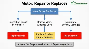
Repair or replace decision:
- If windings show open circuits (infinite resistance) or shorts (near-zero resistance), replacement is typically more cost-effective than rewinding
- If brushes are completely worn but windings test good, brush replacement may be economical if parts are available
- If commutator is severely damaged (deep scoring, segments lifted), motor replacement is required
- Consider unit age and overall condition—if approaching 10–20 year service life, replacement prevents near-term failure of other components
If the Problem Is Control or Driver Related
Signs of control issues:
- Motor and potentiometer both function correctly when tested independently
- System doesn't respond to control commands or responds incorrectly
- Position doesn't match commanded setpoint despite functional components
- Intermittent operation that doesn't correlate with mechanical position
Troubleshooting steps:
- Verify control signal voltage and polarity at driver circuit input using multimeter or oscilloscope
- Check driver circuit board for obvious damage: burned components, cracked traces, or bulging capacitors
- Test limit switches or position feedback sensors for proper operation
- Verify control signal timing—some systems require minimum pulse width or specific signal sequences
- Check for ground loops or electrical noise on signal lines
- Inspect all connectors for corrosion, bent pins, or poor contact
Configuration verification:
- Confirm control parameters match the specific motorized potentiometer model (voltage, resistance, rotation range)
- Verify voltage ratings for both motor and control circuit match specifications
- Check control logic configuration (normally open vs. normally closed, active high vs. active low)
- Ensure feedback signal scaling matches controller expectations
Step 4: Test and Validate the Fix
Operational testing procedure:
- Reconnect all wiring according to original configuration or wiring diagram
- Apply power and run unit through full travel range at slow speed initially
- Monitor for smooth operation without unusual noise, vibration, or binding
- Check for excessive heating during extended operation (units should remain below 70°C)
Electrical verification:
- Connect multimeter to potentiometer output terminals
- Command motor to various positions throughout travel range
- Verify resistance changes linearly and consistently
- Confirm output voltage or current (if equipped with signal conditioning) matches expected values
- Test at travel extremes to verify proper limit switch or slip clutch operation
Control response testing:
- Send position commands from control system
- Verify motor responds correctly to increase and decrease signals
- Confirm accurate positioning at commanded setpoints
- Test stopping accuracy—unit should stop at commanded position without overshoot
Break-in period monitoring:
Run multiple cycles under normal operating conditions over a defined period (typically 24–48 hours):
- Monitor for any recurrence of original symptoms
- Listen for new or unusual noises indicating improper assembly
- Check for excessive heating that could indicate bearing drag or electrical issues
- Verify consistent position accuracy over repeated cycles
When Should You Fix vs Replace a Motorized Potentiometer?
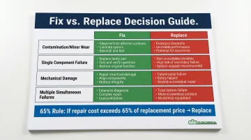
The decision depends on failure severity, component age, repair cost versus replacement cost, and application criticality. As a general rule, industry maintenance standards set a 65% cost threshold: if repair costs exceed 65% of replacement price, replacement becomes the smarter financial choice.
Scenario 1: Contamination or Minor Wear
Fix when: Cleaning and lubrication restore smooth operation and stable resistance readings. The resistive track shows no physical damage under inspection. Gear teeth are intact with minimal wear. Unit is mid-life (5-10 years old) with significant remaining service life.
Replace when: Contamination has caused permanent track damage visible as worn-through spots or cracks. Corrosion has compromised electrical connections beyond cleaning. Multiple cleaning attempts fail to resolve intermittent operation. Environmental conditions will rapidly re-contaminate the unit without improved sealing.
Scenario 2: Single Component Failure (Motor or Potentiometer Element)
Fix when: Only one element (motor OR potentiometer) has failed while the other remains in good condition. Replacement parts are readily available from the manufacturer. Unit is less than 10 years old. Labor costs for repair are reasonable relative to replacement cost.
Replace when: Unit is near end of expected service life (10 or more years old)—the functional component will likely fail soon. Replacement parts are obsolete or require extended lead times. Multiple previous repairs indicate overall degradation. Application is critical and cannot tolerate another near-term failure.
Scenario 3: Mechanical Damage (Gears, Housing, Shaft)
Fix when: Only gears are damaged and exact replacement gears are available. Housing and shaft remain structurally intact. Damage resulted from a single incident (overvoltage, mechanical impact) rather than progressive wear. Cost of gear replacement plus labor remains under 65% of new unit cost.
Replace when: Housing is cracked, warped, or structurally compromised. Shaft is bent, preventing proper alignment. Multiple mechanical components failed simultaneously. Gear damage is severe with metal fragments contaminating other components. Repair costs approach or exceed 65% of replacement cost.
Scenario 4: Intermittent or Multiple Simultaneous Failures
When failures are unpredictable or span multiple systems, the calculus shifts — diagnosis alone can consume more time than replacement justifies.
Fix when: Rarely advisable. Only consider if failure analysis clearly identifies a single root cause (such as voltage spike) that damaged multiple components but can be prevented going forward.
Replace when: Troubleshooting reveals multiple unrelated problems (motor failure plus potentiometer track damage). Intermittent failures cannot be reliably reproduced or diagnosed. Unit has experienced multiple previous repairs. Overall degradation indicates end-of-life condition.
For extrusion applications where downtime is costly, replacement often makes more sense than repeated repairs. OLC's motorized potentiometers carry a 3-year warranty and are built for 10-20+ year service life — meaning a new unit frequently costs less over time than a unit patched past its prime.
Common Mistakes to Avoid When Fixing Motorized Potentiometers
These six mistakes account for the majority of technician-caused damage during repairs. Avoid each one before you start.
Mechanical & Electrical Errors
- Force rotation past the stop point — stripped gear teeth and slip clutch degradation follow immediately. If the shaft won't turn, stop. Repeated forced rotation ruins clutch calibration.
- Apply the wrong lubricant — petroleum-based greases crack plastic gears, and standard oils contaminate the resistive element. Use only manufacturer-recommended damping grease formulated for potentiometers.
- Overvoltage during testing — even brief overvoltage burns motor windings and creates hot spots on resistive elements. Verify voltage specs first, then use a current-limited supply during initial power-up.
Process & Calibration Errors
- Replace parts before diagnosing — swapping components without confirming the failure mode often leaves the root cause intact. Test the motor and potentiometer independently; measure actual values before ordering anything.
- Skip re-lubrication after cleaning — contact cleaners strip protective grease along with contamination. Running a freshly cleaned pot without re-lubricating causes rapid track and wiper wear.
- Adjust the factory-set slip clutch — the clutch is calibrated during manufacturing to protect components while allowing manual override. Tampering voids warranty coverage and results in either premature slippage or loss of over-travel protection.
Preventive Measures to Avoid Future Issues
Inspection Schedules
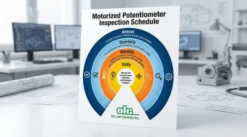
Frequency should match your operating environment and duty cycle:
- Quarterly: Check for physical damage, loose connections, and contamination buildup
- Annually: Test full travel range, resistance linearity, and motor response
- Monthly: Run additional checks in harsh environments (high dust, temperature extremes, or continuous operation)
- Daily: Monitor critical systems for unusual noise, vibration, or performance changes
Environmental Controls
The installation environment directly affects service life. Keep these conditions in check:
- Use enclosures with appropriate IP ratings for the environment (IP65 for dusty conditions)
- Control temperature within the specified range (typically -20°C to +70°C)
- Ensure adequate ventilation to prevent heat buildup in enclosed panels
- Shield units from moisture, chemical vapors, and corrosive atmospheres
- Minimize vibration transmission from nearby equipment
Operating Procedures
How operators handle the unit day-to-day matters as much as environmental factors:
- Never force manual adjustments when the motor is powered — disconnect power before any manual override
- Respect duty cycle limitations to prevent motor overheating
- Keep control signals within specified voltage and current ranges
- Avoid rapid direction reversals that stress the gear train
- Don't exceed rated wiper current when using the potentiometer in rheostat mode
Selecting Quality Components
Prevention starts at the sourcing stage. OLC's motorized potentiometers use Japanese potentiometers, Swiss-made motors and geartrains, and heavy-duty components built for 10–20+ year service life — which translates directly to fewer failures and lower long-term costs. All units carry a 3-year warranty.
Conclusion
Most motorized potentiometer problems can be successfully diagnosed and repaired when approached systematically—testing mechanical drivetrain and electrical functions separately to isolate the specific failure mode. The seven common problems outlined above (erratic readings, motor failures, binding, control issues, calibration drift, and dead spots) each have identifiable symptoms and proven repair procedures.
Staying ahead of failures matters as much as knowing how to fix them. Responding early to symptoms like signal noise, unusual sounds, or position drift prevents minor issues from cascading into complete failures. A basic maintenance rhythm helps:
- Quarterly visual checks to catch mechanical wear and loose connections
- Annual functional testing to identify developing electrical or calibration issues
- Consistent environmental protection and correct operating procedures to extend component life
Knowing when to repair versus replace—based on failure severity, component age, and the 65% cost threshold—is the final piece of the puzzle. Single-component failures in mid-life units typically warrant repair. Multiple simultaneous failures, or units approaching the 10-20 year service mark, make replacement the better long-term investment for keeping production lines running reliably.
Frequently Asked Questions
How do I test a motorized potentiometer with a multimeter?
Disconnect power, then set your multimeter to resistance (ohms) mode and connect leads across the potentiometer's outer two terminals. Rotate the shaft through its full range — resistance should change smoothly with no jumps or infinite readings. Test the motor separately by checking winding resistance (typically 5–50 ohms for DC motors) and applying rated voltage directly to the motor terminals.
Can I manually adjust a motorized potentiometer when power is off?
Yes, most motorized potentiometers include a slip clutch specifically designed to allow manual adjustment without damaging the motor when power is disconnected. The clutch decouples the motor from the potentiometer shaft, enabling manual positioning. Never attempt manual adjustment while power is applied, as this can damage both the motor and gear train.
What causes a motorized potentiometer to drift from its calibrated position?
The most common causes are mechanical wear in the motor-to-shaft coupling, gear backlash in the reduction assembly, or clutch slippage under normal load. Temperature fluctuations can also produce temporary drift in some designs. Inspect the mechanical linkage to pinpoint which wear point is responsible.
How often should motorized potentiometers be serviced or inspected?
Standard industrial environments warrant quarterly visual inspections and annual functional testing of travel range and resistance linearity. High-duty cycle or harsh environments — high dust, temperature extremes, continuous operation — call for monthly checks, with weekly monitoring for noise, vibration, or performance shifts.
What's the typical lifespan of a motorized potentiometer in industrial use?
Quality units like those from OLC typically last 10-20+ years with proper maintenance, though lifespan varies based on duty cycle, environment, and operating conditions. Conductive plastic models offer 10-50 million turns, while wirewound versions provide 500,000 to 2 million turns. Proper environmental protection and adherence to operating specifications maximize service life.
When should I call a professional instead of attempting repair myself?
Reach out to technical support or the manufacturer when multiple failures occur simultaneously, when exact replacement parts aren't available, or when the application is safety-critical. OLC's team can be reached at olc@onlinecontrols.com or 978-562-5353 for direct guidance on diagnosis and sourcing correct parts.