Introduction
Replacing an ETI Systems motorized potentiometer (MC, MAC, or ME series) is moderately technical work requiring careful attention to wiring, mechanical alignment, and system compatibility. Trained technicians and experienced maintenance teams can handle it — but shortcuts during replacement often cause failures that take far longer to diagnose than the replacement itself.
Incorrect replacement leads to problems that aren't always obvious immediately:
- Signal drift or erratic motor behavior
- Shortened component life or control system damage
- Internal binding from over-torqued mounting hardware
- Lost calibration from skipped documentation steps
To avoid those outcomes, this guide walks through the full replacement process — from removing the old unit and installing the replacement, to verifying the system operates correctly before returning it to service.
Key Takeaways
- Replacement covers five steps: isolate power, document wiring, remove the old unit, install the new one, and test
- Confirm series compatibility (MC, MAC, or ME), gather your tools, and know your system's control voltage before starting
- The replacement process typically takes 1-3 hours depending on accessibility and system complexity
- Validate with continuity checks, motor movement tests, and control signal response before resuming operation
- Common mistakes include reversed wiring, incorrect mounting torque, skipping calibration checks, and failing to document original settings
Prerequisites and Safety Considerations
Before beginning replacement, confirm the exact model and series (MC, MAC, or ME) of the existing potentiometer. Verify that the replacement unit matches specifications including resistance value, travel range, and motor voltage. Understand whether your system uses voltage divider or potentiometric output configuration—mismatched specifications guarantee failure.
Safety Requirements
Full system shutdown and lockout/tagout procedures are mandatory under OSHA 29 CFR 1910.147. Discharge any stored energy in connected systems and verify that control voltage is isolated. Motorized potentiometers often connect to PLC or control systems where unexpected voltage can damage sensitive electronics or cause injury.
NFPA 70E requires establishing an Electrically Safe Work Condition (ESWC), which includes disconnecting energized parts, locking/tagging out in accordance with established standards, and verifying the absence of voltage with test equipment.
Documentation Requirements
Document the existing wiring configuration before disconnection:
- Photograph wire positions from multiple angles
- Label each connection point with corresponding terminal numbers
- Record any custom calibration settings or position limits programmed into the control system
- Note wire colors, shielding connections, and ground points
Environmental and Access Considerations
With documentation complete, verify the physical workspace before touching any hardware:
- Adequate clearance around the mounting location
- Ambient temperature within the acceptable installation range (typically 0–50°C)
- Mounting surface stable and free from excessive vibration
When NOT to Proceed
Do not proceed with replacement if:
- Replacement unit specifications don't match original (different resistance, voltage rating, or mechanical travel)
- Mounting hardware is damaged or corroded beyond safe reuse
- Control system documentation is unavailable and wiring cannot be reliably traced
- You lack proper test equipment to validate installation
Tools and Parts Required
Essential Tools
- Multimeter capable of resistance and continuity measurement
- Screwdrivers (typically Phillips and flathead)
- Hex key set for mounting hardware
- Wire strippers and crimping tools if terminal replacement is needed
- Torque wrench if mounting specs require it
Required Parts and Materials
- Replacement ETI motorized potentiometer (verified model match)
- Electrical contact cleaner
- Dielectric grease for connections
- Cable ties or wire management materials
- Replacement mounting hardware only if originals are damaged
Optional But Recommended Items
- Digital camera or smartphone for documentation
- Label maker or masking tape and marker for wire identification
- Anti-static wrist strap if working near sensitive electronics
- Manufacturer's specification sheet for the replacement unit to reference terminal assignments and electrical ratings
How to Replace an ETI Motorized Potentiometer (Step-by-Step)
Replacement follows a disciplined sequence. Each step below builds on the last—skipping ahead or assuming "universal" wiring risks component damage and hours of troubleshooting.
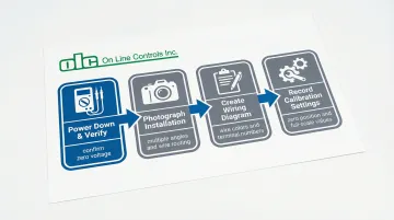
Prepare the System and Document Existing Configuration
Power down the entire control system and follow lockout/tagout procedures. Use your multimeter to verify zero voltage at all potentiometer terminals before proceeding—skipping this step risks electrical shock and equipment damage.
Before touching any wiring, document the existing configuration thoroughly:
- Photograph the unit from multiple angles, capturing wire routing, terminal connections, and mounting orientation
- Create a wiring diagram noting wire colors, terminal numbers, and grounding connections
- For shielded cables, record which end connects to ground—single-point grounding at the signal source prevents electrical noise
- If the system has position display or calibration settings, record current values, zero position, and full-scale readings
Remove the Failed Potentiometer
Carefully disconnect electrical connections one at a time, labeling each wire as you remove it. Remove mounting hardware while supporting the unit to prevent it from falling or putting stress on remaining connections. Inspect the mounting surface for damage, corrosion, or debris that must be addressed before installing the replacement.
Examine the removed unit for obvious failure indicators—burned components, physical damage, shaft binding—that might indicate underlying system issues requiring correction before replacement.
Install the Replacement Potentiometer
Position the replacement unit in the exact orientation as the original. Ensure that mechanical coupling (if present) aligns properly and that shaft travel limits match the application's required range. Shaft coupling misalignment is a primary cause of premature failure—even minor offset reduces service life significantly.
Secure mounting hardware to manufacturer-specified torque if available, or hand-tighten firmly without over-torquing (which can distort the housing and cause internal binding). Verify that the unit sits flush and stable without gaps or misalignment.
Reconnect Electrical Connections
Referring to your documentation, reconnect each wire to its corresponding terminal. Ensure clean contact surfaces and secure connections—for screw terminals, verify that no stray wire strands bridge adjacent terminals.
For DC motor connections (MC and ME series): Two lead wires (typically red and black) control motor direction. Applying positive voltage to the positive terminal results in clockwise rotation when viewed from the front face. Reversing motor leads will cause the unit to drive opposite to control commands.
For AC motor connections (MAC series): Four leads control the reversible motor. Verify correct wiring per your documentation to ensure proper directional response.
Verify that any shielding or ground connections are properly restored. Apply dielectric grease to threaded connectors if specified by manufacturer or if the environment is humid or corrosive.
Post-Replacement Testing and Validation
Validation must occur in stages: electrical verification before power-up, functional testing under no-load conditions, then full system integration. This isolates any issues to specific installation steps rather than surfacing multiple problems at once during production.
Electrical Checks (System Powered Down)
Use your multimeter to verify:
- Correct resistance between potentiometer terminals (should match specification ±10%)
- Continuity of all connections
- No short circuits between terminals or to ground that would indicate wiring errors
IEC 60393 standards define resistance, continuity, and linearity checks that ensure the new component meets operational requirements.
Initial Power-Up Testing
Restore power to the control system only — keep process equipment offline. Then work through these checks:
- Command the potentiometer through its full range of travel and confirm smooth motion with no binding or hesitation
- Verify that the position feedback signal changes linearly and reaches expected minimum and maximum values
- Check for dead spots or signal dropouts, which point to wiper connection issues or contaminated contacts
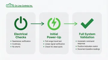
Functional Validation Under Operating Conditions
Bring the full system online and run through typical operating scenarios:
- Verify the potentiometer responds correctly to automatic control commands
- Confirm that position indication matches actual shaft position
- Document baseline readings now — they pay off when diagnosing issues months or years later
Common Replacement Problems and Fixes
Motor Runs Opposite to Control Commands
When the control system commands an increase, the motor drives toward minimum position — or vice versa. This typically means motor drive wires were connected with reversed polarity.
To fix:
- Power down the system and swap the two motor drive wire connections at the potentiometer terminals
- Retest to confirm direction matches commands
- If the system uses a motor controller with directional settings, check those configuration parameters before rewiring
Erratic Position Signal or No Signal Change
The control system receives no position feedback, or the signal jumps erratically rather than changing smoothly. Common causes include a loose wiper connection, reversed wiring on the three-terminal resistive element, or oxidized contacts reducing electrical continuity.
To fix:
- Verify all three potentiometer signal wires are secured to the correct terminals per your wiring documentation
- Clean terminal contacts with electrical contact cleaner if oxidation is visible
- Use a multimeter to confirm resistance changes smoothly as you manually rotate the shaft
Mechanical Binding or Limited Travel Range
The motor struggles through its full range, stops short of expected limits, or produces unusual noise. This usually points to mounting misalignment, an improperly seated coupling, or over-torqued hardware distorting the housing.
To fix:
- Loosen mounting hardware slightly and confirm the unit seats naturally without force
- Check that any mechanical coupling has proper clearance and alignment
- Rotate the shaft by hand through its full range to confirm free movement before restoring motor power
- Verify that travel limit settings in the control system match the potentiometer's mechanical range
Pro Tips for Successful Replacement
Create a replacement checklist specific to your installation before starting work. Include model verification, tool preparation, documentation steps, and sign-off requirements so rushed or after-hours jobs don't skip critical steps.
When sourcing replacement potentiometers, consider lead time and supplier reliability. Keeping one spare unit on hand prevents extended downtime. Motorized potentiometers designed for 10-25 year service life reduce long-term replacement frequency and maintenance costs compared to lower-quality alternatives that fail every few years.
Thorough documentation is just as important as the replacement itself. File the following with your equipment maintenance records:
- Dated before/after photos of the installation
- Wiring diagrams annotated for your specific setup
- Test results confirming correct operation post-replacement
- Notes on any anomalies observed during the swap
This record speeds up future replacements, simplifies technician training, and helps you spot patterns if failures recur ahead of schedule.
Conclusion
Replacement quality directly affects system reliability, control accuracy, and whether you'll be replacing the same component again in months versus years. Every shortcut taken during installation shows up later as a troubleshooting problem — usually at the worst possible time.
Thorough preparation, careful documentation, and validation testing add time upfront — but that time comes back quickly. A correctly installed motorized potentiometer should run reliably for years without revisiting. If you're unsure about any step or run into unexpected behavior during testing, On Line Controls is reachable at olc@onlinecontrols.com or 978-562-5353.
Frequently Asked Questions
How do I know when my ETI motorized potentiometer needs replacement?
Common symptoms include erratic position signals, motor failure to respond to commands, unusual noise during operation, or physical damage. Intermittent issues often indicate impending failure and should be addressed before complete breakdown occurs.
Are ETI MC, MAC, and ME series motorized potentiometers interchangeable?
No. While they share similar form factors, each series has specific electrical and mechanical specifications that must match your application. MC and ME series require DC power (6-24 VDC) while MAC series requires AC power (115 VAC). Always verify resistance value, motor voltage, and travel range before substituting one series for another.
What tools do I need to replace an ETI motorized potentiometer?
Essential tools include a multimeter, screwdrivers, hex keys, wire strippers, and documentation materials (camera, labels). Most replacements don't require specialized equipment beyond standard electrical maintenance tools, though a torque wrench is helpful if mounting specifications are available.
How long does it take to replace an ETI motorized potentiometer?
Typical replacement takes 1-3 hours depending on accessibility, system complexity, and documentation thoroughness. PLC-integrated systems require additional time for calibration and validation testing.
Can I replace an ETI motorized potentiometer myself or do I need a specialist?
Trained maintenance technicians or engineers with electrical and mechanical aptitude can handle replacement following proper procedures. For systems integrated with PLCs or safety circuits — particularly where documentation is incomplete — bring in a specialist.
What are the most common mistakes when replacing motorized potentiometers?
The most frequent errors are:
- Reversed motor wiring, which causes opposite directional response
- Skipping electrical verification before powering up
- Failing to confirm replacement unit specs match the original
- Over-torquing mounting hardware or misadjusting the clutch