Introduction
In plastic extrusion and industrial manufacturing, getting remote speed or position adjustments wrong — even briefly — can mean scrapped product runs. Motorized potentiometers solve this by enabling automated, PLC-driven positioning without any manual operator intervention at the machine.
Wiring one correctly requires handling two separate signal paths: the analog position feedback going to the PLC input, and the motor control wiring that physically moves the potentiometer.
This article covers the complete wiring process — including connection diagrams for common PLC types, voltage and current considerations, safety requirements, and troubleshooting tips specific to motorized potentiometer installations.
Key Takeaways
- Motorized potentiometers have 5-6 terminals: three for position feedback, two for motor control
- Wire the wiper to a PLC analog input (0–10V or 4–20mA); connect motor terminals to digital outputs or relays
- Key to success: match voltages, identify terminals correctly, and calibrate after installation
- Used in plastic extrusion lines to automate setpoint adjustments for air pressure, temperature, or speed
How to Wire a Motorized Potentiometer to a PLC
Step 1: Identify All Terminals on the Motorized Potentiometer
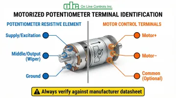
Motorized potentiometers typically have 5–6 terminals divided into two functional groups. The first group consists of three terminals for the resistive element: Terminal 1 (one end), the Wiper (middle terminal), and Terminal 3 (opposite end). The second group includes two or three motor terminals: Motor +, Motor −, and sometimes a common ground.
Always consult the manufacturer's datasheet to confirm which terminals correspond to potentiometer function versus motor function. For example, OLC's motorized potentiometers feature standardized configurations with two 6-inch lead wires (one red, one black) attached to the motor for DC models. Some AC models include integrated circuit boards with clearly labeled terminals for COM, CCW, B, and CW connections.
Terminal confusion is the most common cause of installation failure. Never assume terminal functions based on position alone—incorrect connections can short-circuit the motor or damage the analog input module.
Step 2: Wire the Potentiometer Position Feedback to PLC Analog Input
Connect the potentiometer's three resistive terminals to the PLC analog input as follows:
- Terminal 1 connects to the excitation voltage source (typically +10VDC or +24VDC depending on PLC specifications)
- Terminal 3 connects to ground/common
- Wiper terminal connects to the PLC's analog input channel, reading voltage proportional to position (0–10V range)
Critical consideration: Verify the PLC analog input's voltage range and input impedance. Modern industrial PLCs like the Rockwell ControlLogix 1756-IF16 offer >10 MΩ input impedance on voltage inputs, preventing signal loading that causes non-linear readings. The Siemens S7-1200 SM 1231 provides ≥9 MΩ impedance, while Omron NX-AD series features ≥1 MΩ—all sufficient for standard potentiometer applications.
For longer cable runs or electrically noisy environments, use the 4–20mA output option instead of voltage mode. Current loop signals are immune to voltage drop and loading effects, provided the loop resistance stays within the drive capability (typically 500Ω maximum).
Step 3: Wire the Motor Control Terminals
How you wire the motor terminals depends on whether you need one-direction or full bidirectional control.
For unidirectional control (single direction only):
- Connect the motor's positive terminal to a PLC digital output or relay module capable of supplying the required motor voltage and current
- Connect the motor's negative terminal to ground
- OLC's DC motorized potentiometers typically operate at 6VDC, 12VDC, or 24VDC with optimal current draw of 5–20mA
For bidirectional control (clockwise/counterclockwise rotation):
- Use an H-bridge circuit or dual-relay configuration
- Connect each relay to separate PLC digital outputs
- Configure one output for "Increase" (CW) and another for "Decrease" (CCW)
- Use Phoenix Contact PLC-RSC series relays (rated for 6A continuous) to handle motor loads while protecting the PLC from inductive kickback
Motor current verification: Most transistor output modules (Rockwell 1756-OB16, Siemens SM 1223) are rated for 0.5A per point. For small DC motors this is borderline—use an interposing relay to protect PLC modules from inrush currents and voltage spikes.
Step 4: Implement Safety and Limit Controls
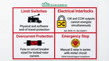
Four safety measures are required before commissioning any motorized potentiometer installation:
- Limit switches — Install physical end-of-travel switches or configure software limits to prevent over-rotation. OLC's MC46-2 and MAC4RC include integrated snap-action switches that trip automatically at minimum and maximum position.
- Electrical interlocks — NFPA 79 (Section 9.11) and IEC 60204-1 require that contactors driving opposing motion be both mechanically and electrically interlocked. In PLC ladder logic, use XIC/XIO instructions so "Increase" and "Decrease" outputs can never energize simultaneously.
- Overcurrent protection — Add a fuse or circuit breaker in the motor power line sized for locked-rotor current. This protects against shorts or motor failure without nuisance tripping during normal operation.
- Emergency stop — Wire a manual E-stop switch in series with the motor control circuit. Follow OSHA 1910.147 lockout/tagout procedures when servicing remotely controlled equipment.
Step 5: Configure PLC Programming for Position Feedback and Motor Control
Stable positioning requires three elements in your PLC program: accurate scaling, deadband logic, and rate limiting.
Analog input scaling: Program the PLC to read the analog input and scale it to engineering units—for example, converting a 0–10V input to 0–100% position or 0–10 units matching physical dial markings. Most PLCs include built-in scaling instructions that map raw ADC counts directly.
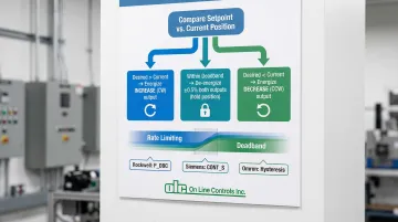
Position control logic: Activate motor outputs based on setpoint comparison:
- Desired position > current position → energize motor in "Increase" direction
- Desired position < current position → energize motor in "Decrease" direction
- Within deadband range → de-energize both outputs
Deadband implementation (CRITICAL): Without deadband logic, the motor oscillates ("hunts") around the setpoint, causing premature mechanical wear. Recommended instructions by platform:
- Rockwell: P_DBC (Deadband Controller) with configurable range
- Siemens: CONT_S (Step Control) with built-in
DEADB_Wparameter - Omron: Advanced temperature control units with explicit hysteresis settings
Set deadband to at least ±0.5% of full range. If signal noise measures ±0.05V, set deadband to ±0.1V to suppress twitching.
Rate limiting: Add rate-of-change limits (ramping) on control outputs to prevent instantaneous direction reversals that stress mechanical components.
Step 6: Test, Calibrate, and Document the Installation
Commissioning covers three phases: functional testing, calibration, and documentation.
Initial power-up: Verify that the analog input reading changes smoothly as the potentiometer adjusts. Monitor for jumps, dead zones, or non-linearity that indicate wiring issues or signal loading.
Motor function test: Run the motor in both directions (if applicable) and confirm that:
- The PLC correctly interprets position changes
- The motor stops at the desired setpoint
- Limit switches engage before mechanical end-stops
- Deadband prevents oscillation around the setpoint
Calibration: Adjust scaling factors or offset values in the PLC program so position readings match physical dial markings. For applications requiring higher precision than the potentiometer's standard <0.15% linearity, use software linearization to map raw inputs to corrected engineering units.
Documentation: Record all terminal connections, PLC I/O assignments, voltage levels, calibration settings, and deadband values. Include wiring diagrams, terminal identification photos, and PLC program backups for future reference and troubleshooting.
When Should You Use a Motorized Potentiometer with a PLC?
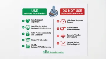
Motorized potentiometers are ideal when remote or automated adjustment is needed without the precision requirements of servo or stepper systems. They offer a cost-effective solution for applications requiring modest precision (typically 0.25% resolution) and simple setpoint control.
Typical use cases include:
- Controlling air pressure in plastic tubing extrusion lines
- Adjusting process temperature setpoints from a central HMI
- Regulating motor speed in conveyors or material handling equipment
- Setting flow rates in chemical dosing systems
- Trimming analog control loops in HVAC or industrial ovens
When NOT to use motorized potentiometers:
- Applications requiring high-speed response — servo systems handle these better
- Extremely precise positioning requirements (sub-millimeter accuracy)
- Environments with excessive vibration that could damage the motor or potentiometer mechanism
- Applications requiring dynamic motion profiles rather than simple setpoint positioning
Understanding these limits helps clarify where motorized potentiometers genuinely shine. Once the target setpoint is reached, the device holds its position mechanically through friction, consuming zero power. No active control loop is needed — a servo, by contrast, must continuously draw power to maintain position.
What You Need Before Wiring a Motorized Potentiometer to a PLC
Getting the right components and documentation in place before you start saves time and prevents costly mistakes during installation.
Equipment and Components
Confirm your motorized potentiometer specs before selecting the rest of your components:
- Resistance value (e.g., 10kΩ) compatible with your application
- Voltage rating matched to available power supplies
- Motor voltage, current draw, and directional control requirements
- OLC's motorized potentiometers cover resistance ranges from 10Ω to 100KΩ, with DC motor options at 6V, 12V, or 24V
Your PLC must meet minimum analog input requirements for a clean signal:
- At least one analog input (0–10V or 4–20mA) with appropriate input impedance
- One or two digital outputs (or relay modules) capable of driving the motor
- Rockwell ControlLogix 1756-IF16: >10 MΩ impedance, 16-bit resolution
- Siemens S7-1200 SM 1231: ≥9 MΩ impedance, 12-bit resolution
- Omron NX-AD series: ≥1 MΩ impedance
For power supplies, plan for two separate circuits unless voltages match:
- One for potentiometer excitation (typically 10VDC or 24VDC)
- One for motor operation (may share the same supply if voltage ratings align)
- Size for adequate current capacity — motors typically draw 200mA running, with peaks up to 500mA
Tools and Safety Equipment
Gather these before starting:
- Multimeter for measuring voltages, continuity, and verifying connections
- Wire strippers, screwdrivers, and crimping tools
- Terminal blocks or connectors sized to your wire gauge
- Shielded twisted-pair cable (e.g., Belden 9536) for analog signal wiring
- Safety glasses and insulated gloves
- Lockout/tagout devices if working near energized industrial equipment
Documentation and Knowledge Requirements
Have the following documentation on hand before you begin wiring:
- Manufacturer datasheets for both the motorized potentiometer and PLC
- Wiring diagrams and terminal identification guides (OLC provides diagrams on request)
- Analog signal scaling and conversion references for your specific input range
- Basic motor control logic and relay operation knowledge
- PLC programming fundamentals: ladder logic and analog I/O instructions
Key Parameters That Affect Results When Wiring a Motorized Potentiometer to a PLC
Several electrical and mechanical factors influence system accuracy, reliability, and longevity.
Potentiometer Resistance Value and PLC Input Impedance
The potentiometer's resistance must be compatible with the PLC analog input's impedance to avoid signal loading. When a PLC input with insufficient impedance connects to the wiper, it creates a parallel resistance path that causes non-linear voltage readings.
Three resistance ranges cover most applications:
- Lower resistance potentiometers (100Ω–1kΩ) draw more current but resist electrical noise well
- Higher resistance values (50kΩ–100kΩ) draw minimal current but are prone to interference pickup
- 10kΩ is the most common compromise — good noise immunity without excessive current draw
Standard PLC voltage inputs (>1 MΩ impedance) handle 10kΩ potentiometers without loading effects. For critical applications, verify that the PLC input impedance is at least 100 times greater than the potentiometer resistance.
Motor Voltage and Current Requirements
Motor ratings must match available power supplies, and current draw must stay within PLC output or relay capacity.
Voltage tolerance is narrow — under-voltage causes weak or stalled motor operation, while over-voltage accelerates wear or causes immediate damage. OLC's DC motorized potentiometers operate at 6V, 12V, or 24V with ±10% tolerance.
Current capacity requires equal attention:
- Verify motor current draw against PLC output ratings (typically 0.5A per point)
- Use interposing relays rated for 6A continuous (Phoenix Contact PLC-RSC series) for robust installations
- Account for inrush current — motors may draw 2–3x running current during startup
Analog Signal Range and Scaling
Matching the potentiometer's output voltage range to the PLC analog input's range maximizes resolution and accuracy.
A 16-bit ADC on a ±10V range provides ~320 µV/count resolution. Using only 0–5V of a 0–10V input wastes half that resolution, so configure the potentiometer excitation voltage to match the PLC input range exactly.
Scaling in the PLC program deserves equal care:
- Improper scaling causes incorrect position readings or a limited control range
- Verify scaling calculations by measuring actual voltage at several known positions
- Document scaling factors and offset values — they save significant troubleshooting time later
Motor Control Method (Unidirectional vs. Bidirectional)
Control method selection impacts wiring complexity, PLC programming, and system capabilities.
Unidirectional motors keep things simple — single PLC output, lower cost, and minimal wiring. The tradeoff is that position adjustment only runs in one direction.
Bidirectional motors offer full positioning control but add complexity:
- Require polarity reversal through an H-bridge or dual relay configuration
- Need two PLC outputs with interlock logic to prevent simultaneous activation
- OLC's motorized potentiometers support bidirectional operation with reversible motors
The interlock logic is non-negotiable. If both forward and reverse outputs energize at the same time — a "shoot-through" condition — the result is a short circuit and potential equipment damage.
Environmental Factors and Mechanical Limits
Operating environment directly affects both potentiometer accuracy and motor performance.
Four environmental factors most commonly cause field problems:
- Temperature extremes affect resistance values and motor efficiency
- Humidity leads to corrosion on terminals and wiper contacts
- Vibration produces erratic readings or accelerated mechanical wear
- EMI/RFI from variable frequency drives or welding equipment corrupts analog signals
Addressing these early is cheaper than troubleshooting them later. Use shielded twisted-pair cable for all analog wiring, grounded at one end only (typically the PLC chassis). Select enclosures rated IP65/IP67 or NEMA 4/4X for industrial environments, and confirm the installation location meets OLC's specified operating range of -15°C to +65°C.

Mechanical limits:
- Physical or electronic limit switches prevent over-rotation and mechanical damage
- OLC's slip clutch mechanism protects end stops and prevents gear train breakage
- Software limits in PLC logic provide an additional protection layer
Common Mistakes When Wiring a Motorized Potentiometer to a PLC
Mixing Up Motor and Signal Terminals
Confusing motor terminals with potentiometer signal terminals is one of the fastest ways to damage a system. It can blow PLC analog inputs, burn motor windings, or destroy the power supply. Always verify each terminal's function against the manufacturer's datasheet before making a single connection.
Undersizing the Motor Power Supply
An underpowered supply causes insufficient torque, erratic movement, and voltage drops that corrupt analog signal accuracy. Size the power supply for at least 150% of the motor's maximum current draw to handle inrush current. If the motor and analog circuit share a supply, introduce filtering capacitors or switch to separate supplies to prevent noise from bleeding into the signal.
Skipping Limit Switches and Software Limits
Without physical limit switches or configured PLC logic limits, the potentiometer can over-rotate — stripping gears or cracking the resistive element. Even OLC's factory-set slip clutch mechanisms don't eliminate the wear caused by repeated over-rotation. Protect the unit with both hardware end stops and PLC travel limits. Redundant protection is not overkill here; it directly extends service life.
A quick checklist before powering up:
- Confirm all terminal IDs against the datasheet
- Verify power supply rating at 150%+ of motor draw
- Test limit switch actuation before full-speed operation
- Confirm PLC software limits are active in the control program
Troubleshooting Issues When Wiring a Motorized Potentiometer to a PLC
Problem: Analog Input Reads Zero or Maximum Value Constantly
Common causes include an open circuit at the wiper terminal, a damaged resistive element, or misidentified terminals.
To diagnose:
- Use a multimeter to check continuity between wiper and end terminals with power off
- Measure resistance between Terminal 1 and Terminal 3 (should match potentiometer rating)
- With power on, measure voltage at the PLC analog input with potentiometer at mid-position (should read approximately half of excitation voltage)
- Verify wiring connections are tight and terminals are not corroded
Problem: Motor Does Not Run When PLC Output is Activated
This usually points to a power supply issue, reversed polarity, a blown fuse, or a seized motor. Start here:
- Measure voltage at motor terminals when PLC output is active (should match motor rating)
- Check for correct polarity on DC motors (red = positive, black = negative)
- Verify motor current draw is within power supply and PLC output ratings
- Test motor independently with a bench power supply to confirm functionality
- Inspect for mechanical binding or any obstruction that prevents rotation
Problem: Position Reading is Non-Linear or Jumps Erratically
Erratic readings typically stem from impedance loading, electrical noise, worn contacts, scaling errors, or ground loops in shielded cable.
Steps to isolate the cause:
- Check PLC input impedance specifications (should be >100x potentiometer resistance)
- Replace standard cable with shielded twisted-pair, grounded at PLC end only
- Measure analog signal voltage directly at the potentiometer terminals and compare to PLC reading
- Review and verify scaling factors in PLC program
- Clean potentiometer contacts or replace unit if mechanical wear is evident
- Add a 0.1µF capacitor across the analog input to filter high-frequency noise
Problem: Motor Oscillates or "Hunts" Around Setpoint
Hunting behavior is almost always a control logic issue — deadband too narrow, tuning too aggressive, or mechanical backlash amplifying small signal variations.
To stabilize:
- Increase deadband tolerance in PLC program (try ±1% of range initially, then optimize)
- Reduce motor speed if adjustable to allow more settling time
- Add rate limiting to prevent rapid direction changes
- Inspect mechanical components for excessive play or wear
- Verify that both forward and reverse outputs are not energizing simultaneously due to faulty interlock logic
Conclusion
Wiring a motorized potentiometer to a PLC involves connecting both the analog position feedback circuit and the motor control circuit, with careful attention to voltage ratings, terminal identification, and safety measures. Success depends on proper component selection, correct wiring practices, and well-designed PLC control logic with adequate deadband to prevent oscillation.
Most failures trace back to three preventable issues:
- Terminal confusion during installation
- Undersized motor power supply that can't handle startup loads
- Missing calibration or limit controls that leave the system without bounds
Follow the step-by-step procedures in this guide and implement proper safety interlocks — those two steps alone eliminate most field failures.
This control method is well-suited to plastic extrusion lines, where OLC's motorized potentiometers handle remote setpoint adjustment with the precision and durability these processes demand. With a three-year warranty and a documented service life of 10–20 years, properly installed systems require little intervention once commissioned.
Frequently Asked Questions
How does a motorized potentiometer work?
A motorized potentiometer combines a standard variable resistor with a small electric motor. The motor rotates the potentiometer's shaft to change resistance and output voltage, allowing remote or automated position adjustment via PLC control. A slip clutch mechanism protects the end stops while enabling manual override when the motor is off.
What are the 3 pins on a potentiometer?
The three pins are: Terminal 1 (connected to supply voltage), the Wiper (middle terminal providing variable output), and Terminal 3 (connected to ground). Wiper voltage varies linearly with shaft position between the two end terminals.
Can I use a standard PLC digital output to drive the motor directly?
Most PLC digital outputs provide only 100-500mA, which is insufficient for many motors. OLC's DC motorized potentiometers draw just 5-20mA, making direct connection feasible in some cases — but a relay module or solid-state relay is still recommended for protection and long-term reliability.
What voltage should I use to power the potentiometer and motor?
The potentiometer typically runs at 10VDC or 24VDC to match the PLC analog input. The motor uses its own rated voltage — commonly 12VDC or 24VDC for DC models, or 115VAC for AC models. Always verify current capacity against the manufacturer datasheet for both circuits.
How do I prevent the motor from damaging the potentiometer by over-rotating?
Install physical limit switches at the potentiometer's travel extremes and program software limits in the PLC to stop motor operation when position feedback reaches minimum or maximum allowable values. Many motorized potentiometers include built-in slip clutches and optional snap-action switches for automatic end-of-travel protection.