How to Build a Potentiometer Position Sensor Circuit That Reads Stable - Google Drive
Potentiometers are still one of the simplest ways to sense position. The circuit around them is where most builds fail.
If you’re feeding a pot into an ADC, PLC, or controller, this guide shows the wiring patterns that actually hold up outside the bench.
You’ll learn the three baseline potentiometer position sensor circuits: divider-only, divider + buffer, and divider + RC filter, and when to combine them. You’ll also see when the environment forces a step up (long runs/industrial noise).
By the end, you’ll have a quick decision checklist and a simple verification workflow you can run before you lock hardware.
Key Takeaways
A potentiometer position sensor circuit starts as a 3-wire voltage divider: Vref → pot → GND, with the wiper feeding your input.
Divider-only works only when the input doesn’t load the wiper, and the wiring/noise is under control.
If readings shift or compress, add a buffer (op-amp follower) to isolate the pot from the ADC/PLC input.
If readings jitter, add a simple RC filter (and fix wiring/routing) to trade a bit of response time for stability.
Verify before you commit: check endpoint voltages, mid-travel linearity, and look for dropouts/jumps that signal a worn or noisy pot.
What circuit do you need for a potentiometer position sensor?
A potentiometer position sensor circuit starts with one simple idea: treat the pot as a 3-wire voltage divider. When you wire it correctly, the wiper produces a voltage that tracks position, clean, predictable, and easy to read with an ADC or PLC analog input.
The baseline circuit: 3-wire voltage divider
Connect one end terminal to Vref (your reference/supply for the measurement).
Connect the other end terminal to GND.
Connect the wiper (middle pin) to your ADC/analog input (Vout).
As the shaft moves, the resistance splits across the two halves of the track, and the wiper voltage moves between ground and Vref. In ideal conditions:
0% travel ≈ 0V
100% travel ≈ Vref
Mid-travel ≈ Vref/2
Why “ratiometric” matters (and saves you from drift)
If your ADC measures the wiper using the same Vref that powers the divider, your reading becomes ratiometric. That means small Vref shifts (supply variation) don’t change the percentage reading much, because both the numerator (Vout) and denominator (Vref) move together.
Practical translation:
If your controller lets you choose the ADC reference, using the same reference supply you feed the pot with usually makes the signal more stable.
What “position” maps to in the real world
In practice, the wiper won’t always hit a perfect 0V and Vref:
Mechanical end stops can prevent reaching the electrical endpoints.
Pot tolerance and track geometry can introduce small offsets.
Wiring and input loading can compress the range (we’ll cover that next).
So think of the signal as “near 0 to near Vref” unless you’ve verified the endpoints on your specific setup.
The most common wiring mistakes (and how to spot them fast)
Swapped end terminals: The reading still works, but direction is inverted (clockwise gives lower voltage instead of higher).
Wrong pin for the wiper: The signal becomes stuck near 0 or near Vref, or behaves like a switch.
No common ground: Readings jump randomly or sit at nonsense values (especially with separate power supplies).
Quick sanity check:
With power on, measure wiper voltage at both mechanical endpoints. You should see a clear change from low to high (or high to low if inverted).
Once the divider is wired correctly, the next failure mode is usually not wiring it’s whether your ADC/PLC input loads the wiper and distorts the signal.
When does a divider-only circuit fail?
A divider-only potentiometer circuit is the right starting point. It fails when the wiper voltage stops behaving like a clean, stable signal at the input you’re feeding. That usually happens because the input loads the wiper or the ADC sampling action disturbs the node, not because the pot “suddenly became inaccurate.”
The wiper is a changing source impedance.
The wiper isn’t a regulated output. It’s a voltage divider node with source impedance that changes with position. At mid-travel, the resistance to both ends is highest in combination, so the wiper becomes easier to disturb.
What this means in practice: the same circuit can look fine at one end and drift/jitter in the middle.
The three most common “divider-only” failure signatures
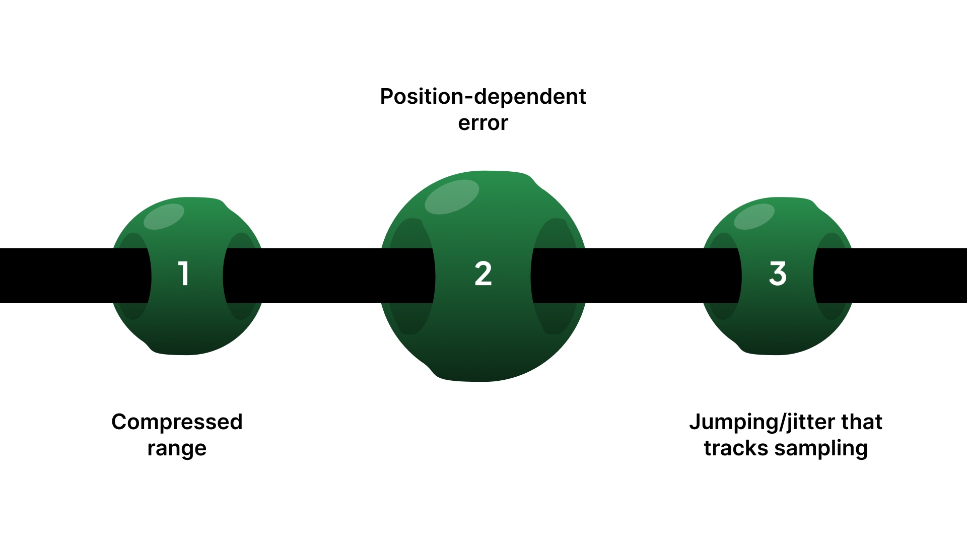
If the pot is wired correctly but the circuit is wrong for the input, you’ll typically see:
Compressed range: You don’t get near 0V and near Vref at the ends (even though the pot turns fully).
Position-dependent error: One region reads “about right,” another region shifts noticeably.
Jumping/jitter that tracks sampling: The value gets worse when you sample faster or when the controller scans inputs.
These symptoms point to interaction at the wiper node, not a basic wiring issue.
ADC sampling effects on the wiper node
Many ADC inputs don’t draw steady current, but they charge a sampling capacitor during conversion. If the wiper’s source impedance is high, that charging pulse can momentarily pull the node, which looks like noise or steps in the reading.
Quick field check: if readings improve when you slow the sample rate or add a small series resistor/buffer, the wiper is being disturbed by the input.
Practical guideline for ADC input drive
Most PLC/MCU ADC inputs behave like a switched-capacitor load (sample-and-hold). During the acquisition window, the ADC briefly connects an internal sampling capacitor to your signal.
If the source impedance seen at the ADC pin is too high, the capacitor can’t settle to the true voltage before conversion.
That shows up as steps, extra jitter, or position-dependent error (often worst mid-travel).
Rule of thumb: If you can’t increase the ADC/PLC acquisition time, don’t rely on divider-only when the effective source impedance is “high” (high-value pot, long wiring, extra series resistance, multiplexed channels, fast scan rate).
In those cases, buffer the wiper, or add a small “charge-bucket” capacitor at the ADC input (with a small series resistor) so the ADC can charge quickly and repeatably.
Pot value choice: stability vs power
Pot value influences how vulnerable the wiper node is:
Too high (e.g., 100k+): Easier to disturb, more sensitive to noise and ADC sampling effects.
Too low (e.g., 1k): Draws more current continuously and wastes power; can add heating in some setups.
Practical default: 10k is often a safe starting point unless your input spec says otherwise.
Decision point: choose the circuit by the failure mode you’re seeing
If you’re seeing range compression or sampling-linked jitter, you’re at the point where a divider-only circuit usually isn’t enough. The next step is picking the simplest upgrade that matches your environment.
Potentiometer position sensor circuit options: when to use each
Circuit option | Best when | Common failure mode | What to add/change | Typical trade-off |
|---|---|---|---|---|
Divider-only (direct to ADC) | Short wiring, clean environment, high-impedance input | Jitter, range compression, mid-travel instability | Lower pot value (within reason) or move to buffer | Simplest, but least robust |
Divider + buffer (op-amp follower) | Input loads the wiper or ADC sampling disturbs the node | Compressed range, steps/jumps with sampling | Add a unity-gain buffer close to the pot | Adds parts + requires power |
Divider + RC filter | Small jitter, but response speed isn’t critical | Noise that looks random, a small ripple | Add an RC low-pass at the right node | Adds lag/response delay |
Buffer + RC filter | Noisy environment + you need a stable ADC source | Jitter plus sampling artifacts | Buffer first, then filter | More parts, slower response |
Divider + transmitter (industrial runs) | Long cable runs / harsh EMI / remote sensing | Noise pickup, ground offsets | Convert to conditioned/industrial signal | Higher complexity + cost |
Now that you can identify when divider-only fails and what circuit to move to, the next step is the most common upgrade: a simple buffer that isolates the wiper without overdesigning the system.
Buffer circuit options that make the signal stable
If your divider-only circuit fails, the cleanest fix is usually a buffer. A buffer doesn’t “improve” the potentiometer; it isolates the wiper so the ADC/PLC input can’t load it or disturb it during sampling.
The simplest correct buffer: unity-gain follower
Use an op-amp as a voltage follower:
Pot wired as a divider (Vref → pot → GND)
Wiper → op-amp non-inverting input (+)
Op-amp output → ADC/analog input
Op-amp output tied back to inverting input (–) (unity gain)
What it does:
Makes the wiper look like a low-impedance source to the ADC.
Eliminates most range compression and position-dependent loading error.
Reduces sampling “kicks” from ADC sample-and-hold behavior.
What to look for in a buffer op-amp
For typical 3.3V and 5V control systems, prioritize:
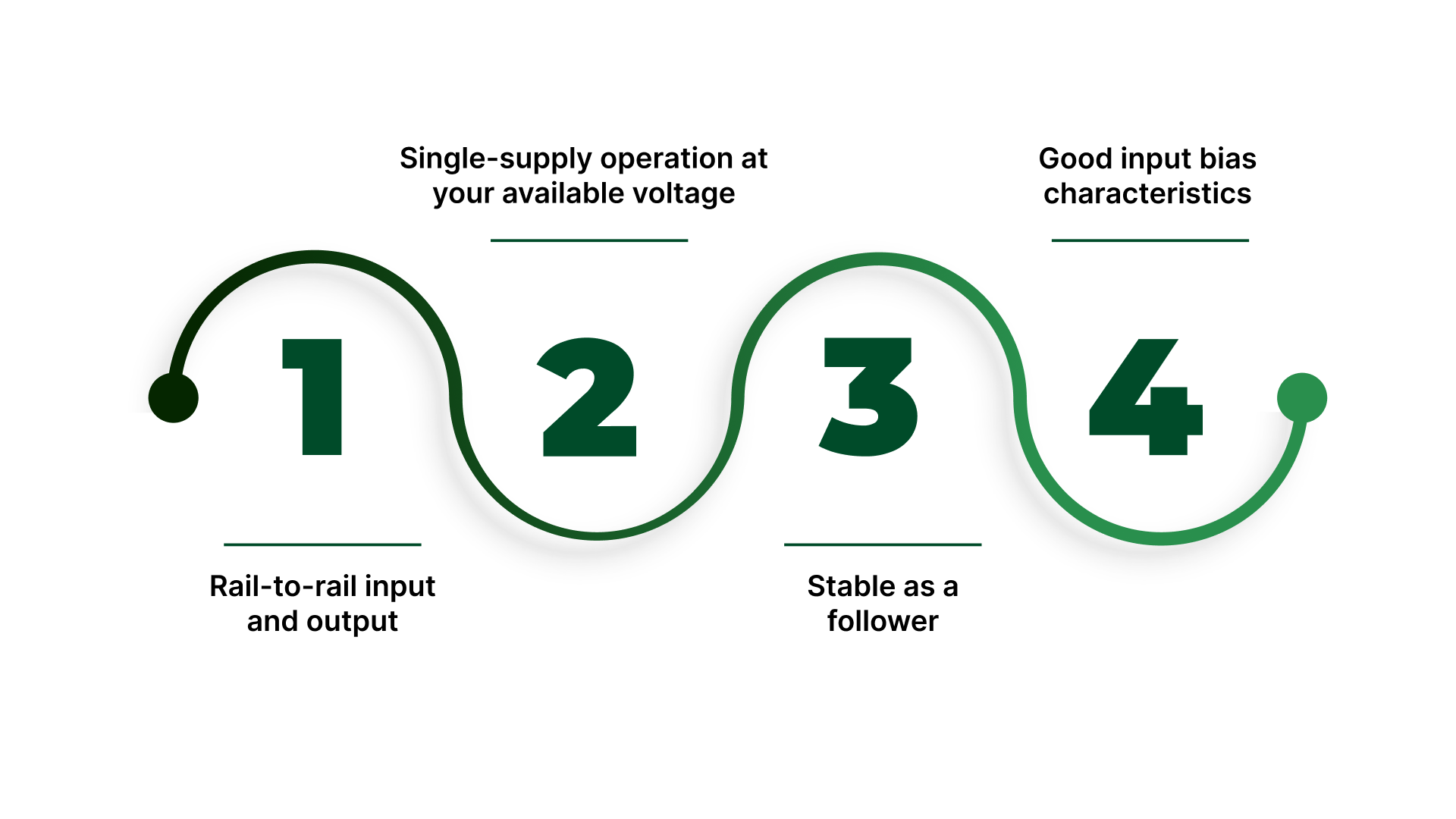
Rail-to-rail input and output (so you can measure near-ground and near-Vref without clipping)
Single-supply operation at your available voltage
Stable as a follower (some op-amps dislike unity gain without the right conditions)
Good input bias characteristics (so it doesn’t introduce its own offset at the wiper)
If your signal needs to reach very close to 0V or Vref, rail-to-rail matters more than most people expect.
Buffer placement: where you put it matters
Put the buffer as close to the potentiometer as practical, especially if the wiring run to the controller is long.
A buffer at the controller end doesn’t protect the wiper node from noise pickup along the cable.
Simple rule: buffer the signal before it travels.
Basic input protection
If you’re worried about miswiring or transients, the common minimal protection stack is:
A small series resistor between the buffer output and the ADC input (limits surge current)
Clamp protection (either the controller’s internal clamps or external diodes, depending on your design)
You’re not trying to build a surge suppressor here, just prevent a mistake from killing the input.
When a buffer still won’t solve it
A buffer fixes the loading and sampling interaction. It does not fix:
EMI pickup from long cables near motors/VFDs
Grounding issues that inject noise into the signal reference
Mechanical wear/noisy tracks inside a worn potentiometer
If your reading is still bouncing after buffering, treat it as an environment and wiring problem first.
How to reduce noise and jitter?
If your potentiometer position signal “bounces,” the cause is usually one of two things: electrical noise getting into the wiring, or a signal that’s too high-impedance / too fast for your input environment. The fix is a mix of basic filtering and boring-but-critical installation choices.
The simplest RC low-pass filter (and where to put it)
A basic RC low-pass filter smooths fast voltage changes so your controller sees a steadier value.
Most common placement: Add a series resistor in the signal path and a capacitor to ground at the measurement node.
Where it helps most:
At the ADC/analog input node, especially when the cable run is picking up noise.
After a buffer, if you’re using one (this keeps the filter predictable and prevents interaction with the pot’s changing source impedance).
Where it can hurt: If you place aggressive filtering right at the wiper on a high-value pot, you can create lag and make the node more sensitive to certain disturbances. Keep it simple: filter where the input is read, and don’t overdo the values.
The real trade-off: smoother reading vs slower response
Filtering always costs you something: response time.
Light filtering: reduces small jitter but still tracks motion quickly.
Heavy filtering: looks stable, but your control loop feels “behind,” especially if position changes fast.
Quick sanity rule: if your system needs fast motion feedback, don’t “fix” noise by adding huge capacitors. Fix the wiring and reference first, then filter lightly.
Wiring practices that reduce noise more than extra components
These often do more than the RC filter:
Keep the signal run short where possible.
Use twisted pair for signal + ground return (reduces loop area).
If the environment is noisy, use shielded cable and connect the shield intentionally (avoid random multi-point shield connections).
Route pot wiring away from VFD/motor leads, contactors, solenoids, and switching power wiring.
Make sure the pot and controller share a solid reference ground (a floating or noisy ground makes every reading look unstable).
In most real panels, “mystery jitter” is a routing/grounding issue, not a circuit mystery.
Noisiest real-world sources (and what to do first)
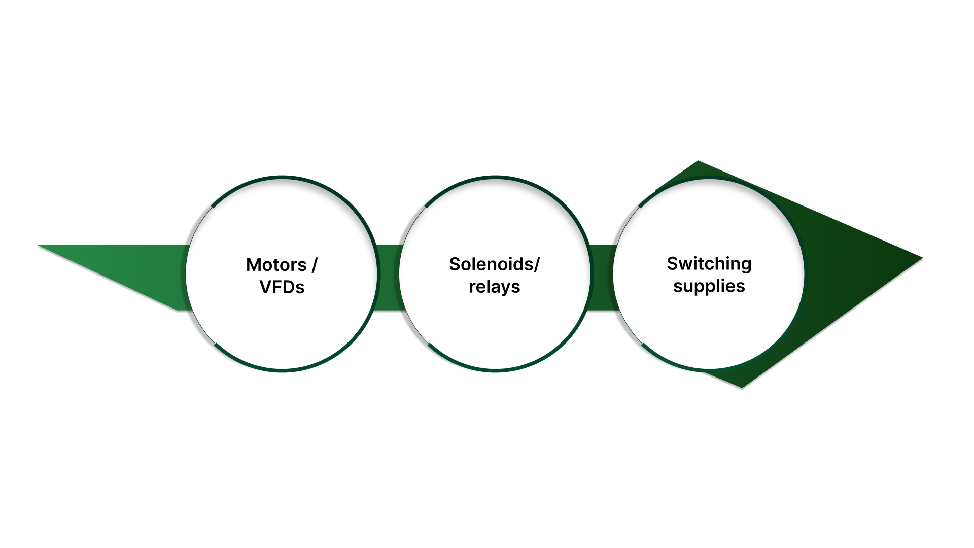
Motors / VFDs: move the pot cable away from motor leads, use shielded twisted pair, and consider buffering + light filtering.
Solenoids/relays: add suppression at the source (coil suppression) and keep signal wiring separate.
Switching supplies: check grounding and routing; don’t let pot return currents share dirty power returns.
Start with separation and grounding first, then add filtering. If you filter a dirty signal path, you usually just hide the problem until it shows up as lag.
Once the circuit is stable, you still need to confirm it’s reading correctly across travel and catch issues like dead spots or drift early.
How to verify the circuit?x
Before you put a potentiometer position signal into a control loop, verify three things: it’s wired correctly, it’s stable, and it repeats. This section is meant to be copy/paste friendly—run it once and you’ll know whether you’re dealing with a circuit issue, an environment issue, or a worn potentiometer.
Quick verification checklist
Wiring + reference
Confirm the pot is wired as a divider: Vref → end terminal, GND → other end, wiper → input.
Confirm that the controller/ADC and the pot share a common reference ground.
Confirm Vref is stable (not sagging under load or drifting with other loads switching).
Endpoint sanity check
Move to one mechanical end stop: record Vout.
Move to the other end stop: record Vout.
You should see a clear low-to-high swing. It may not be exactly 0V and Vref, but it should be consistent and repeatable.
If the endpoints are inconsistent, don’t calibrate yet; fix wiring/reference or loading first.
Linearity sanity check (0/25/50/75/100%)
This catches “looks fine at the ends but wrong in the middle” issues.
Mark or measure 5 repeatable positions: 0%, 25%, 50%, 75%, 100% travel.
Record Vout at each point moving upward, then repeat moving downward.
What “normal” looks like:
Values increase smoothly with position.
The up and down readings are close (minor differences are normal due to mechanical play).
No sudden voltage dropouts or spikes.
If mid-travel behaves worse than the ends, suspect loading, ADC sampling interaction, or a noisy/worn track.
“Is my pot bad?” fault tests
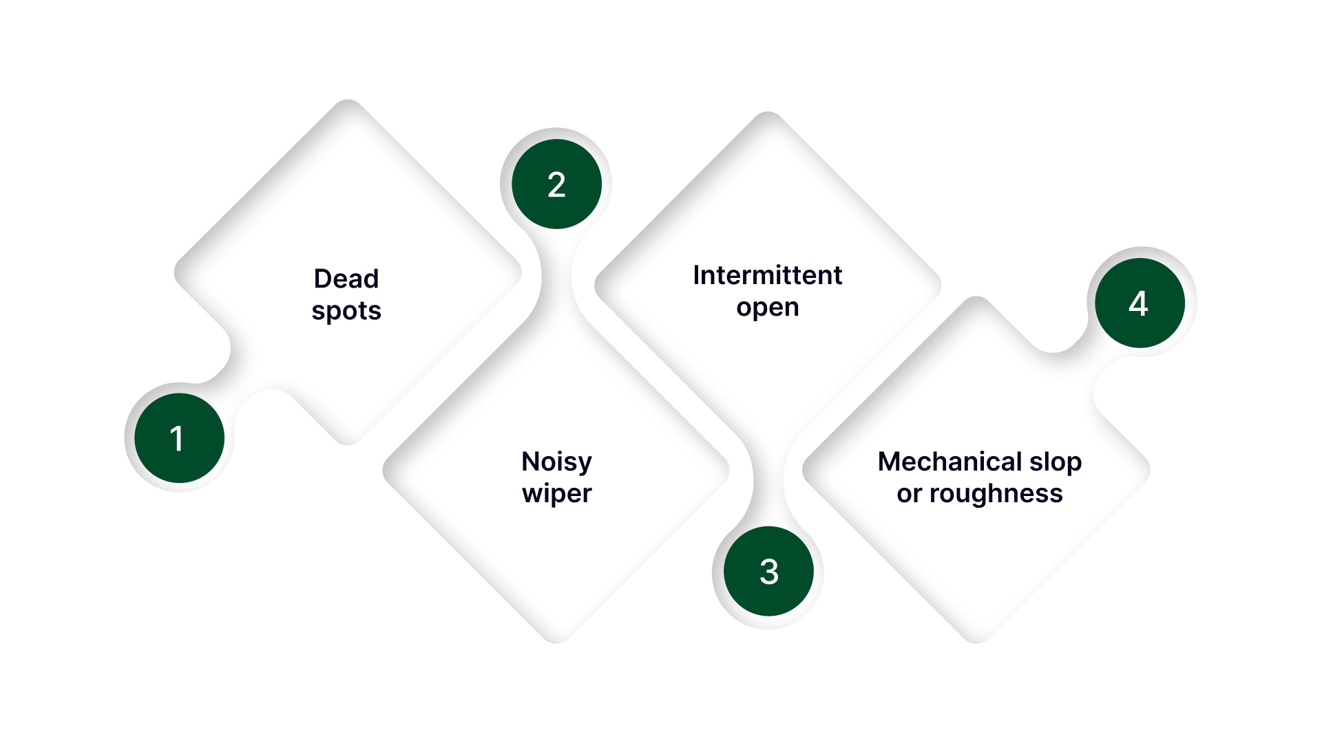
These symptoms usually indicate a worn or failing potentiometer:
Dead spots: voltage doesn’t change for a portion of travel or jumps abruptly.
Noisy wiper: small movement causes large random changes even after filtering.
Intermittent open: signal occasionally snaps to 0V or Vref, then returns.
Mechanical slop or roughness can correlate with erratic readings.
A quick confirmation: measure resistance end-to-end (should be steady) and wiper-to-end while moving slowly (should change smoothly). Erratic resistance change usually matches erratic voltage.
Drift checks
If this is going into a real machine, do two quick stress checks:
Temperature soak: run it warm/cold (even a basic “cold start vs warmed up” check) and verify endpoints + mid-travel again.
Vibration/cable movement: gently flex the cable and harness while holding the shaft steady. If the reading jumps, the issue is wiring/shielding/grounding—not the pot element.
When to switch approaches
Consider a different sensing approach (or a more robust conditioning interface) if:
You need high repeatability in a harsh EMI environment with long runs.
Mechanical wear will be a limiting factor (high cycling, dirty environment).
You need absolute accuracy and long-term stability beyond what a contact-based wiper can maintain.
If your verification checklist shows the circuit is right but you’re still fighting drift, noise, wear, or you need repeatable remote adjustment, the limiting factor is usually the potentiometer hardware and integration, not the schematic.
What On Line Controls does
Help you choose a potentiometer setup that matches your signal range and reference so your ADC/PLC reads full travel cleanly (no “compressed range” surprises).
Provide motorized potentiometers when you need controlled, repeatable position changes without manual tweaking.
Support integration details that affect stability in the real world: mounting, travel limits, wiring approach, and environment fit.
Offer options that align with common control setups (AC/DC motor drives and positioning use cases).
Why teams use this support
Application-focused guidance for control/automation scenarios (not generic electronics advice).
Broad range coverage of motorized potentiometers and accessories suited to industrial environments.
Practical troubleshooting support tied to symptoms like jitter, drift, dead spots, and long-run wiring issues.
Want a quick “will this read stable?” check?
Send these inputs, and we’ll confirm the right potentiometer approach and the simplest circuit path:
Controller input type (PLC analog / ADC) + reference voltage (3.3V/5V/10V)
Required travel (degrees/turns) + how fast the position changes
Cable length + noise sources nearby (VFD/motor/solenoid)
Current symptoms (jitter, drift, range compression, dead spots)
Any constraints (mounting space, environment, need for motorized adjustment)
Conclusion
A potentiometer position sensor circuit is simple in concept: a voltage divider that maps travel to voltage. The reliability problems start when the wiper gets loaded by the input, disturbed by ADC sampling, or polluted by noise from long cables and real-world wiring.
If you want stable readings, build it in this order: wire the divider correctly, verify your reference and endpoints, then add the smallest upgrade that matches the failure mode buffer for loading/sampling issues, RC filtering for jitter (after you fix routing and grounding), and a transmitter-style approach for harsh or long-run installs.
Use the verification checklist to prove the signal holds across travel, restarts, and basic stress checks. Once the circuit is right, the last limiter is often the hardware itself, wear, mounting, or the need for repeatable adjustment. Lock those choices early, and you avoid the classic cycle of “works today, drifts tomorrow.”
FAQs
How do you wire a potentiometer as a position sensor?
Wire it as a 3-wire voltage divider: one end to Vref, the other to GND, and the wiper to your ADC/PLC input. If your ADC uses the same Vref as its reference, the reading stays ratiometric and more stable.
What is the output signal of a potentiometer position sensor circuit?
It’s a variable voltage proportional to position, typically ranging from near 0V to Vref. Endpoints don’t always hit a perfect 0/Vref due to tolerances and mechanical stops, so verify the real travel range.
What potentiometer value is best for an ADC input (10k vs 100k)?
10k is often a safe default because it’s less sensitive to noise and behaves better with ADC sampling. 100k can increase jitter and sampling artifacts; very low values waste power and may warm the track.
Do I need an op-amp buffer for a potentiometer sensor circuit?
Use a buffer when the input loads the wiper or ADC sampling causes jumps/steps. A unity-gain follower isolates the pot, typically fixing range compression and position-dependent errors.
How do you reduce noise in a potentiometer position sensor reading?
Fix wiring first: keep runs short, route away from VFD/motor leads, and use shielded/twisted pair where needed. Then add a light RC filter if you can accept some response lag—filtering won’t compensate for poor routing or grounding.