Introduction
When a 30-year-old extrusion line stops mid-production because a potentiometer fails, finding an exact replacement becomes urgent. Many manufacturing systems from the 1980s-2000s remain operational today, but their potentiometers are now obsolete or degraded.
Heavy machinery can operate for 50 years. The electromechanical interfaces governing speed, position, and calibration fail first, forcing manufacturers to hunt for discontinued parts or risk extended downtime.
The stakes are high: unplanned downtime costs automotive manufacturers up to $2.3 million per hour, while oil and gas operations face losses near $1 million per hour [source needed].
Finding exact replacements for discontinued parts while maintaining equipment performance now represents a strategic priority, not just a repair task.
This guide covers how to identify, source, and replace obsolete potentiometers in industrial equipment, and when modernization makes more sense than direct replacement.
Key Takeaways
- Match 5 critical specifications: resistance value, taper, mechanical dimensions, power rating, and tolerance
- Equipment lifespan (20-40+ years) exceeds standard potentiometer life (5-15 years)
- Motorized potentiometers offer 10-25 year lifespans versus 5-15 years for standard analog units
- Installation demands documentation, compatibility checks, and ESD precautions
How to Replace Obsolete Potentiometers in Legacy Industrial Equipment
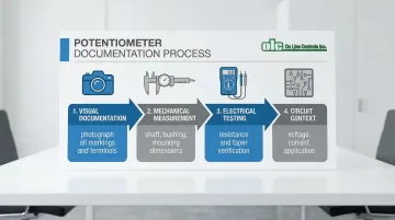
Step 1: Document the Existing Potentiometer Specifications
Photograph the potentiometer from multiple angles showing all markings, part numbers, and terminal configurations before removal. This visual documentation becomes critical when the original manufacturer's cross-reference guides are incomplete or the part number is partially worn.
Measure and record mechanical dimensions with precision:
- Shaft length, diameter (common: 6mm, 6.35mm, 1/4"), and profile (round, D-shaft, flatted)
- Bushing thread size (typical: 3/8-32 UNF or M9 x 0.75)
- Panel thickness compatibility
- Mounting hole spacing
Use a multimeter to measure actual resistance between terminals. Verify the taper type by checking resistance at 25%, 50%, and 75% rotation points—if the midpoint reads approximately 50% of total resistance, you have a linear taper; if it reads 10% or 90%, it's logarithmic.
Document the electrical circuit context including input voltage, current load, and whether it's used for signal control or power regulation.
This information determines power rating requirements and helps identify potential compatibility issues.
Step 2: Research Replacement Options and Cross-References
Search the original manufacturer's obsolescence notices and suggested replacement part numbers using your documented part number. Manufacturers like Bourns issue Product Obsolescence Memos (POMs) that specify recommended replacement series or last-time-buy windows.
Industrial component distributors offer parametric search tools to narrow your options:
- Filter by resistance, tolerance, taper, power rating, shaft diameter, bushing thread, and IP rating
- Mouser, Digi-Key, and RS Components provide comprehensive search capabilities
- Review multiple candidates to compare specifications and availability
Contact the original equipment manufacturer for recommended service parts or engineering change notices. For critical legacy components, specialized suppliers maintain motorized potentiometer lines specifically for industrial equipment. Companies like On Line Controls manufacture motorized potentiometers and rheostats designed as direct retrofits for obsolete ETI Systems and other legacy brands from the 1980s-1990s, offering precise control solutions for equipment modernization.
Step 3: Verify Compatibility and Order Sample Units
Create a specification comparison table between the obsolete part and potential replacements, flagging any differences in:
- Resistance value and tolerance
- Taper type (linear vs. logarithmic)
- Power rating (typical: 0.05W to 2W)
- Mechanical fit (shaft, bushing, mounting)
- Environmental ratings (temperature range, IP rating)
Order 2-3 sample units of the most promising candidates before committing to bulk orders, especially for critical production equipment. Test samples in a non-production environment or during scheduled maintenance windows to verify electrical performance and mechanical fit.
Confirm that replacement parts meet industry-specific requirements such as CE compliance, UL ratings, or IP ratings for washdown environments. Industrial potentiometers typically require IP40 for the body and IP65 for the shaft/bushing interface to prevent dust and water ingress.
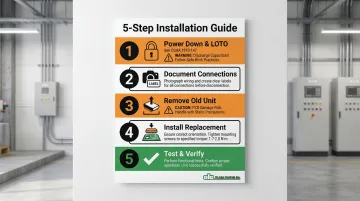
Step 4: Perform the Replacement with Proper ESD Precautions
Power down equipment completely and follow lockout/tagout (LOTO) procedures per OSHA 1910.147. Discharge any stored energy in capacitors before beginning work—this prevents both personal injury and damage to sensitive components.
Remove the old potentiometer carefully, documenting wire connections with labels or photographs. For through-hole components, use desoldering braid or a solder sucker to avoid PCB damage.
Follow IPC J-STD-001 standards with maximum soldering temperatures of 399°C (750°F) for 3 seconds.
Install the new potentiometer ensuring proper orientation, secure mounting, and correct terminal connections. Verify that shaft coupling or linkages align properly with control mechanisms. Apply appropriate torque to mounting hardware—typically 1.7 to 2.0 N-m (15-18 lb-in) for panel-mount pots. Overtightening strips threads or cracks the housing; under-tightening leads to component rotation and wiring stress.
When Should You Replace vs. Modernize Industrial Potentiometers?
Direct replacement makes sense when equipment is nearing end-of-life (5-10 years remaining), budget is constrained, or the existing control scheme is adequate for current production needs.
This approach minimizes upfront costs and engineering time while maintaining familiar operation for plant personnel.
Modernize with motorized or digital potentiometers when:
- Equipment will operate 10+ years more
- Remote control capability is needed for safety or efficiency
- You're implementing automation or Industry 4.0 initiatives
- Frequent manual adjustments create bottlenecks or inconsistency
Total Cost of Ownership Comparison
When evaluating replacement options, compare these key factors:
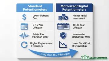
Standard Potentiometers:
- Lower upfront cost
- Expected lifespan: 5-15 years
- Subject to vibration and mechanical wear
- Higher frequency of future replacements
Motorized/Digital Potentiometers:
- Higher initial engineering investment
- Expected lifespan: 10-25 years
- Immune to vibration and mechanical wear
- Lower total cost of ownership over equipment lifetime
Factor in downtime costs for future replacements when calculating true TCO.
What You Need Before Replacing Obsolete Potentiometers
Poor preparation causes most replacement failures, compatibility issues, and extended downtime. Successful potentiometer replacement requires careful planning across five categories.
Documentation and Measurement Tools
- Digital multimeter for resistance and continuity testing
- Calipers for precise mechanical measurements (±0.01mm accuracy)
- Camera for visual documentation of markings and wiring
- Equipment service manual or wiring diagrams
Once you've gathered diagnostic tools, secure the physical components for installation.
Replacement Parts and Installation Materials
- Verified compatible replacement potentiometer(s)
- Appropriate solder and flux for through-hole installations
- Thermal compound if heat dissipation is critical
- Mounting hardware if not included with replacement unit
Safety and technical support resources protect both personnel and equipment during the replacement process.
Technical Resources and Safety Equipment
- Use ESD wrist strap and mat for sensitive electronics (per IEC 61340-5-1)
- Apply lockout/tagout procedures for electrical safety
- Contact information for technical support from parts supplier or OEM
Even with proper preparation, unexpected complications can extend replacement time significantly.
Contingency Planning
- Backup potentiometer in case first replacement fails
- Scheduled maintenance window (plan for 2-3x expected duration)
- Alternative production arrangements if equipment remains down
Finally, ensure your team has the technical capabilities to complete the work safely and correctly.
Skills and Expertise Requirements
- Technician trained in electronics repair and soldering techniques
- Understanding of the equipment's control system architecture
- Authorization to modify production equipment per facility protocols
Key Parameters to Match When Sourcing Replacement Potentiometers
Potentiometers have multiple interdependent specifications—missing even one parameter can result in poor performance or complete incompatibility.
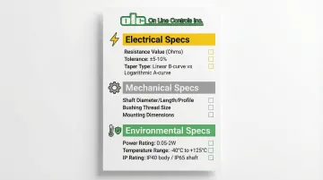
Electrical Specifications
Resistance value (measured in ohms/kilohms) must match exactly as this determines the control range and signal levels. Standard industrial values include 1 kΩ, 5 kΩ, and 10 kΩ. Verify both the nominal value and tolerance rating—industrial potentiometers typically feature ±5% or ±10% tolerances versus ±20% in consumer electronics.
Taper type affects how output changes with rotation:
- Linear (B-curve): Resistance changes proportionally with rotation—standard for most industrial controls, sensors, and VFD speed references
- Logarithmic (A-curve): Resistance changes exponentially—designed for audio applications and generally unsuitable for industrial process control
Mismatched tapers cause non-linear or unintuitive control behavior.
A logarithmic taper in a VFD speed control loop creates extreme sensitivity at one end and unresponsiveness at the other.
Mechanical Specifications
Beyond electrical compatibility, physical dimensions must align with your existing equipment.
Shaft configuration must match existing knobs and couplings:
- Diameter: Common sizes include 6.0mm (metric) and 6.35mm (imperial)
- Length: Measured from bushing face to shaft end
- Profile: Round, D-shaft (flatted), or slotted for screwdriver adjustment
Mounting specifications determine physical fit:
- Bushing thread size and length (common: 3/8-32 UNF or M9 x 0.75)
- Mounting hole spacing for multi-hole configurations
- Panel thickness requirements
Power and Environmental Ratings
Power rating (typically 0.05W to 2W) must meet or exceed the circuit's requirements. Underrated parts will overheat and fail prematurely. Industrial panel controls are often rated for 1 Watt at 70°C, derating to 0 Watts at 125°C.
Environmental specifications should match operating conditions:
- Operating temperature range: Typical industrial range of -40°C to +125°C
- IP rating: Standard IP40 body with IP65 shaft for dust and water protection
- Vibration and shock resistance: Per MIL-STD-202 (typical: 15G vibration, 30G shock)
Common Mistakes When Replacing Obsolete Potentiometers
Replacing obsolete potentiometers requires precision. Avoid these common pitfalls that lead to downtime and calibration failures:
Assuming "close enough" specifications will work — Even 10% resistance variations cause calibration issues or error codes in automated systems. Match specifications exactly or verify compatibility through testing before installation.
Failing to verify taper type — Linear and logarithmic pots are often mechanically identical but produce completely different control responses. Verify taper by measuring resistance at the 50% rotation point to avoid wasted time and reinstallation costs.
Skipping pre-installation testing — Installing untested replacement parts during critical operations creates unnecessary risk. Always validate replacements during scheduled maintenance or in a test fixture first. The cost of testing is minimal compared to unplanned production downtime.
Troubleshooting After Potentiometer Replacement
After replacement, testing under actual operating conditions often reveals issues not apparent during bench testing. The following diagnostic steps address the most common post-installation problems.
Control Response is Non-Linear or Erratic
Likely cause: Taper mismatch between original and replacement potentiometer.
Check the resistance curve at 25%, 50%, and 75% rotation positions. If values don't increase proportionally, you may have a logarithmic taper instead of linear (or vice versa).
Replace with the correct taper type—there is no workaround for this fundamental incompatibility.
Equipment Shows Error Codes or Won't Calibrate
Likely cause: Resistance value or tolerance is outside the control system's expected range.
Diagnostic steps:
- Verify the total resistance matches specification exactly
- Check for cold solder joints or poor connections adding resistance
- Measure resistance in-circuit if possible (use a high-impedance multimeter, as circuit loading can affect readings)
Mechanical Binding or Inconsistent Feel
Likely cause: Shaft misalignment with coupling mechanism or incorrect mounting torque.
Corrective steps:
- Loosen mounting hardware and verify shaft alignment with linkages or gears
- Re-torque to specification (typically 1.7-2.0 N-m)
Excessive torque can warp the potentiometer body, causing the wiper to bind against the resistive element.
Frequently Asked Questions
How do I find a replacement for an obsolete potentiometer?
Start by documenting all specifications from the original part, then search manufacturer cross-reference guides and contact industrial component distributors with parametric search capabilities that can identify functional equivalents.
What can be used instead of a potentiometer?
Motorized potentiometers offer remote control and longer lifespan (10-25 years). Digital encoders provide infinite resolution without wear. Modern digital control systems can retrofit into existing equipment depending on architecture.
What is the lifespan of a potentiometer?
Industrial potentiometers typically last 5-15 years depending on usage intensity and environmental conditions. Conductive plastic types offer 10-50 million turns, while wirewound units provide 1-4 million turns. Carbon composition types wear fastest.
Can I upgrade to motorized potentiometers instead of replacing with analog?
Yes, motorized units often retrofit into existing equipment, providing remote control and 10-25 year lifespans. On Line Controls specializes in direct replacements for obsolete ETI Systems and other legacy potentiometers from the 1980s-1990s.
How do I prevent potentiometer obsolescence in the future?
Choose replacement parts from manufacturers with long product lifecycles and established market presence. Document all specifications thoroughly and maintain spare parts inventory for critical equipment. Consider modernization to current-production motorized or digital controls that offer longer operational lives.
What are the signs that a potentiometer needs replacement?
Watch for scratchy or intermittent operation, inability to achieve full control range, physical damage to shaft or housing, or drift requiring frequent recalibration. Address these during scheduled maintenance rather than waiting for complete failure.