How to Use Potentiometer Position Feedback with a PLC - Google Drive
If you’re using potentiometer feedback for position on a linear actuator, valve, damper, or any motor-driven mechanism, you’re usually trying to answer one simple question: “Where am I right now, and can I trust that reading?”
In practice, issues usually come down to basics: miswiring, poor grounding around PWM motor noise, uncalibrated endpoints, or mechanical play that ruins repeatability.
This guide is written for controls/automation engineers and maintenance teams who need a practical, commissioning-ready approach, not a theoretical lesson.
We’ll keep it focused on what matters in the field: how potentiometer position feedback works, how to implement it as a stable signal your PLC/controller can trust, and how to verify it with quick tests before you sign off.
You’ll walk away with a simple setup flow (wire → scale → calibrate → soft limits), the most common stability failure modes (noise, drift, wear, coupling issues), and a decision checklist that tells you whether to proceed, fix the install, or upgrade the sensing method.
Quick Answer: Potentiometer position feedback
Potentiometer feedback position uses a potentiometer as an analog sensor that reports the mechanism's position to a controller/PLC. Most systems use a 3-wire voltage divider: supply, ground, and a wiper output that varies with travel.
Reliable results require correct wiring + scaling, endpoint calibration, and noise control (EMI + wear). A short commissioning checklist (repeatability, noise, limits, drift) confirms it’s ready under load.
What is potentiometer position feedback?
Potentiometer position feedback is simply using a potentiometer as a position sensor. As the shaft (rotary) or slider (linear) moves, the potentiometer’s wiper changes the output signal. Your controller or PLC reads that changing signal and treats it as “current position.”
This is different from using a potentiometer as a manual knob to set speed or a setpoint. In position feedback, the potentiometer is tied to the mechanism you’re measuring, so the signal represents where the mechanism actually is, not what you want it to do.
Where this approach makes sense:
Linear actuators that provide a feedback potentiometer, or where you can mechanically couple one to the stroke.
Valve and damper position indication where you need a continuous “0–100% open” style signal.
Retrofits where you need a straightforward analog position signal into a PLC without adding a more complex sensor stack.
A quick fit check before you commit:
Duty cycle: If it’s moving constantly or cycling heavily, a contact potentiometer may wear faster than you want.
Environment: Dust, oil mist, washdown, vibration, and temperature swings can reduce stability and life.
Accuracy/Repeatability needs: Pot feedback is often “good enough” for general positioning, but tight tolerances and high repeatability under load can expose backlash and sensor noise.
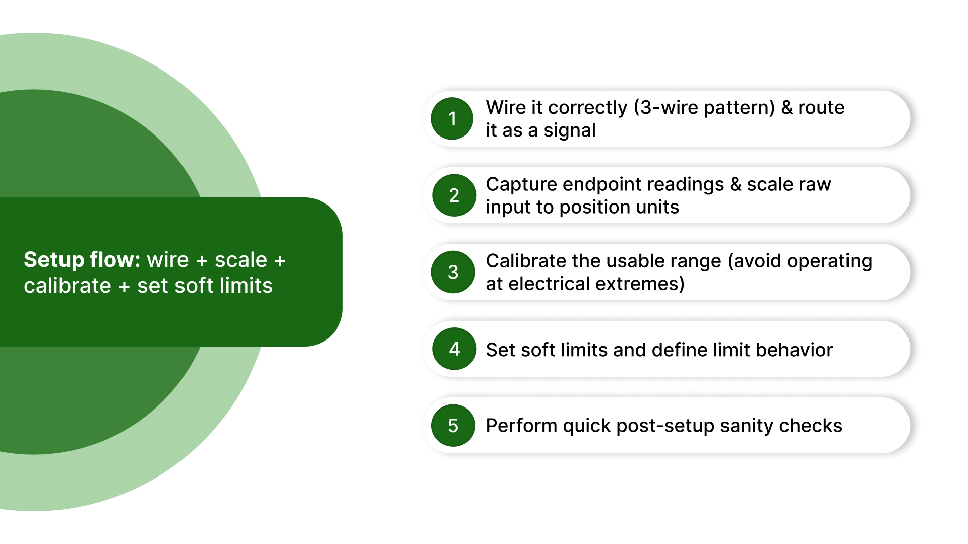
If potentiometer feedback fits your use case, the fastest way to make it reliable is to implement it in one clean setup flow: wire it correctly → scale the signal → calibrate endpoints → set soft limits.
Setup flow: wire + scale + calibrate + set soft limits
To achieve reliable potentiometer position feedback, treat implementation as a commissioning task with defined steps. The goal is to convert the raw wiper signal into a stable, scaled position value that remains consistent and stays within safe limits throughout operation.
Step 1: Wire it correctly (3-wire pattern) and route it as a signal
A position-feedback potentiometer is typically used as a 3-wire voltage divider:
One end to a stable reference supply (often the PLC/controller reference supply)
One end to ground/common
The wiper to the analog input
Two practical requirements often determine success:
Route the potentiometer signal wiring separately from motor leads, contactors, and PWM drive wiring.
Ensure the analog input and potentiometer share a stable reference and ground (inconsistent reference/grounding can appear as false position changes).
Before you scale the signal, confirm the potentiometer value won’t load the analog input or make the wiper signal more noise-sensitive.
Quick check before scaling: pot resistance vs PLC analog input impedance
Rule: The PLC analog input impedance should be significantly higher than the potentiometer resistance so that the wiper voltage remains accurate.
Too high a pot value can be more noise-sensitive. Too low increases the current draw from the reference supply.
If unsure, confirm the PLC input impedance in the datasheet and choose a pot value that keeps loading negligible.
Step 2: Capture endpoint readings and scale raw input to position units
Before running full-stroke motion at production speeds, move the mechanism to known positions and record the raw reading:
Record minimum (fully retracted/closed) and maximum (fully extended/open) values.
Map raw counts/voltage into engineering units (%, mm/in, degrees) using a simple linear relationship.
Clamp out-of-range values (including rail-high/rail-low readings) so abnormal readings do not propagate into control decisions.
This prevents “impossible” values (for example, >100% travel) from being treated as a valid position.
Step 3: Calibrate the usable range (avoid operating at electrical extremes)
Even when the mechanism can physically reach full travel, it is generally best not to operate at the potentiometer’s electrical extremes. Define a usable operating range:
Store an offset/span so the reported “0–100%” corresponds to the intended mechanism travel.
Maintain a small margin at both ends so minor drift, tolerance stack-up, or coupling slip does not push the signal into an unstable region.
Step 4: Set soft limits and define limit behavior
Soft limits provide an additional layer of protection and consistency. Define:
A minimum safe value and a maximum safe value inside the true travel range
Limit behavior, typically: stop motion, optionally apply brake/coast, and raise a fault/alarm for investigation
Soft limits help prevent repeated contact with hard stops and reduce the risk of damage to the potentiometer and mechanism.
Step 5: Perform quick post-setup sanity checks
Immediately after setup, perform two basic checks before relying on the signal:
Monotonic check: As the mechanism moves in one direction, the reading should move smoothly in the expected direction (no reversals, dropouts, or sudden jumps).
Disturbance check: With the motor/drive operating nearby, confirm the reading remains stable; if the signal spikes or intermittently drops out, address wiring/grounding and routing before commissioning.
If wiring, scaling, calibration, and soft limits are correct but the feedback still misbehaves, the next issue is stability noise, drift, and wear.
Stability problems: noise, drift, wear, and mechanical coupling
If potentiometer feedback is wired, scaled, and calibrated correctly but still produces inconsistent results, the root cause is usually one of two things: signal integrity (noise/interference) or mechanical integrity (coupling, backlash, or wear).
Common symptom patterns and what they usually indicate
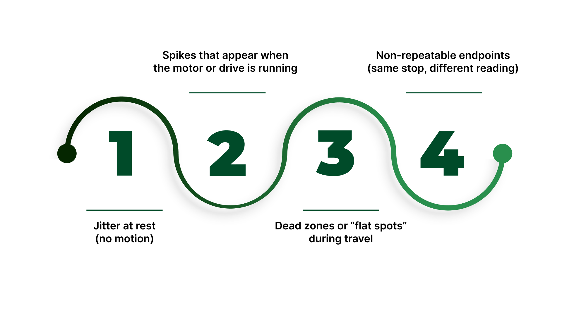
Jitter at rest (no motion): Often reference/ground instability, analog input noise, or a worn wiper/track.
Spikes that appear when the motor or drive is running: Commonly, EMI coupling from PWM motor currents into the potentiometer signal/ground.
Dead zones or “flat spots” during travel: Mechanical binding, damaged track, poor coupling geometry, or operating too close to the electrical ends.
Non-repeatable endpoints (same stop, different reading): Coupling slip, backlash, or a potentiometer that is starting to wear or contaminate.
One wiring fault is worth separating from general noise because it can look like random spikes but is actually a loss-of-signal condition.
Failure detection: open wiper or broken wire
If the wiper opens (broken wire, loose terminal), the analog input can rail high/low or jump, creating “impossible” position values.
Add sanity bounds (min/max plausible raw counts) and fault on out-of-range so a wiring fault doesn’t become a control input.
If your PLC supports it, implement broken-wire detection or a “signal loss” alarm using a timeout / rate-of-change check.
Electrical stability fixes
Without reworking the entire system, these checks usually deliver the fastest improvement:
Confirm a stable reference and common: If the reference supply or ground shifts under load, the position reading will shift with it.
Improve shielding and routing (quick wins): Keep the potentiometer signal away from motor leads and PWM wiring; where needed, use shielding and terminate it correctly to reduce induced noise.
Apply light filtering only after the basics are correct: A small amount of smoothing can reduce jitter, but excessive filtering adds lag and can make control behavior worse (overshoot or oscillation in closed-loop systems).
Mechanical stability fixes
Even a clean analog signal cannot compensate for mechanical variability:
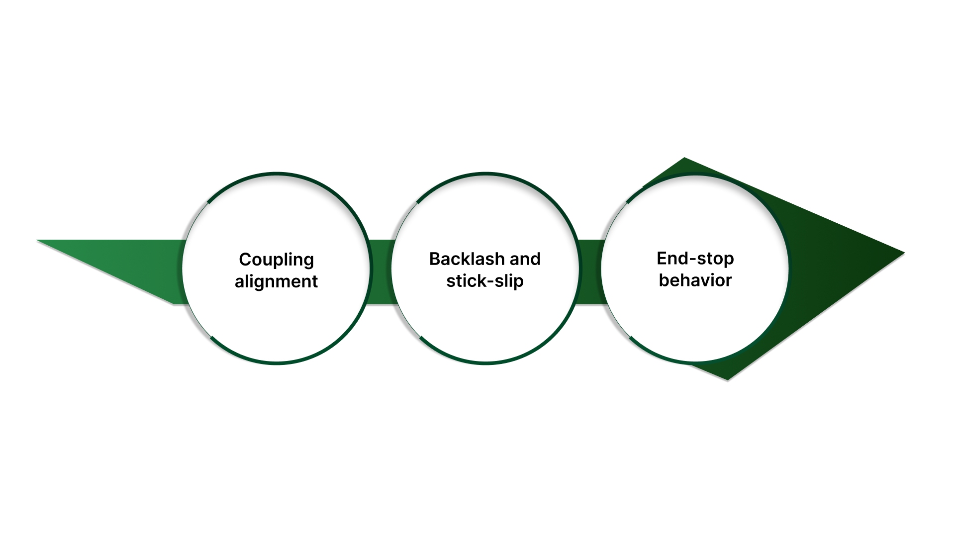
Coupling alignment: Misalignment can introduce non-linear motion, intermittent contact, or uneven wear.
Backlash and stick-slip: If position depends on approach direction (good from one direction, off from the other), backlash or friction effects are likely dominating the error.
End-stop behavior: Repeatedly loading the mechanism into hard stops can accelerate wear and shift the effective calibration over time.
Wear and drift triggers.
A contact potentiometer can degrade gradually or fail intermittently. Watch for:
Intermittent wiper contact (brief dropouts, sudden jumps)
Non-monotonic output (reading decreases while moving forward)
Accelerated degradation under high cycle rates, vibration, contamination, or frequent reversals
At this point, additional filtering or tuning often masks symptoms rather than solving the underlying issue.
Upgrade triggers: when to consider encoder or non-contact sensing
Use these cues to decide if a sensor upgrade is justified:
You require tight repeatability under load and cannot reduce backlash/friction.
The environment or duty cycle causes frequent potentiometer wear or contamination.
Signal stability depends on heavy filtering that introduces unacceptable response delay.
You observe non-monotonic output or intermittent dropouts that persist after wiring and grounding improvements.
If you are deciding whether to retain potentiometer feedback or move to another sensing method, the next section provides a clear comparison to support that decision.
Keep potentiometer feedback or upgrade?
Once the system is implemented correctly, the next decision is whether a potentiometer remains the right feedback device for the application’s accuracy, duty cycle, and environment.
The practical choice is not “best sensor overall,” but “best sensor for the requirement without adding unnecessary complexity.”
When to use potentiometer feedback?
A potentiometer is often the right choice when you need a straightforward, continuous position signal and the operating conditions are moderate:
Simple integration: Analog output is easy to read on many controllers and PLC analog inputs.
Absolute within travel: For a given mechanical coupling and travel range, the signal corresponds directly to position.
Low setup overhead: Commissioning is typically simpler than encoder-based systems when extreme precision is not required.
When to avoid potentiometer feedback?
Consider alternatives when your system consistently pushes the weaknesses of a contact device:
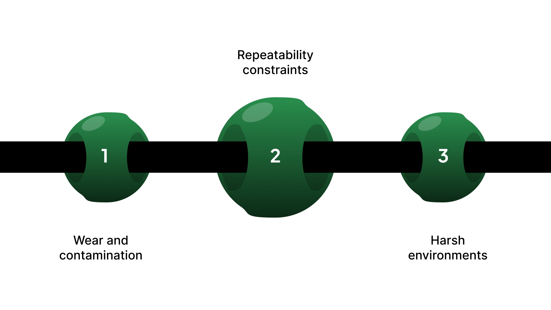
Wear and contamination: High cycle counts, vibration, or contaminant exposure can degrade the wiper/track over time.
Repeatability constraints: Backlash, stick-slip, and coupling variability can dominate error even with a clean signal.
Harsh environments: Washdown, temperature extremes, or aggressive chemicals often reduce service life or stability.
When to use encoder feedback?
Encoders are typically preferred when repeatability, resolution, and long-term stability are the primary constraints:
Higher repeatability/resolution potential for precise positioning and tighter tolerances
Often better suited to high-duty-cycle motion, where contact wear becomes a maintenance issue
Requires more integration planning (signal type, noise immunity, and commissioning procedures)
When to use Hall / magnetic (non-contact) sensing?
Non-contact magnetic sensing can be a strong middle ground when you need better durability than a contact potentiometer without the full encoder stack:
Better tolerance to wear-related failure modes (no wiper contact)
Often effective in dirty or vibration-prone environments where contact sensors degrade
Integration varies by sensor type (analog vs digital outputs), with commissioning implications similar to other sensor upgrades
Integration reality: what changes when you upgrade
Before switching sensors, plan for what will change beyond the sensor itself:
I/O requirements: Analog input vs digital pulse/direction vs networked feedback
Noise and grounding approach: Encoders and digital sensors have different susceptibility patterns than analog signals
Commissioning steps: Homing/reference methods and fault detection often change with the feedback type
Whatever you choose, do not consider the feedback reliable until it passes a short verification checklist under load and in the real electrical environment.
How to verify / decision checklist
Before you rely on potentiometer feedback in production, run a short commissioning checklist under real electrical and mechanical conditions. The goal is not to “prove it works once,” but to confirm it is repeatable, stable, and protected at the limits.
Go / no-go commissioning tests.
Repeatability test (backlash and coupling check)
Command or move to the same target position multiple times from both directions.
Record the final position reading each time.
If results depend on approach direction, suspect backlash, coupling slip, or stick-slip friction.
Noise test (EMI and reference stability check)
Compare the feedback signal with the motor/drive stopped vs running (especially under PWM).
Watch for spikes, jitter bursts, or sudden steps that correlate with motor activity.
If noise appears only during motion, prioritize routing/grounding/shielding corrections before adding heavy filtering.
Limit test (soft limits and fault behavior)
Verify the system stops reliably at the defined soft limits without contacting hard stops in normal operation.
Confirm limit behavior is consistent: motion stops, and the controller raises the intended fault/alarm.
Any tendency to “push into the stop” indicates limit logic, calibration, or scaling needs correction.
Drift/hold test (creep and stability over time)
Hold a fixed position for a defined period and log the feedback value.
Look for slow movement or signal drift that exceeds your allowable tolerance.
Drift can indicate reference/ground shift, thermal effects, or early-stage potentiometer wear.
Decision outcomes
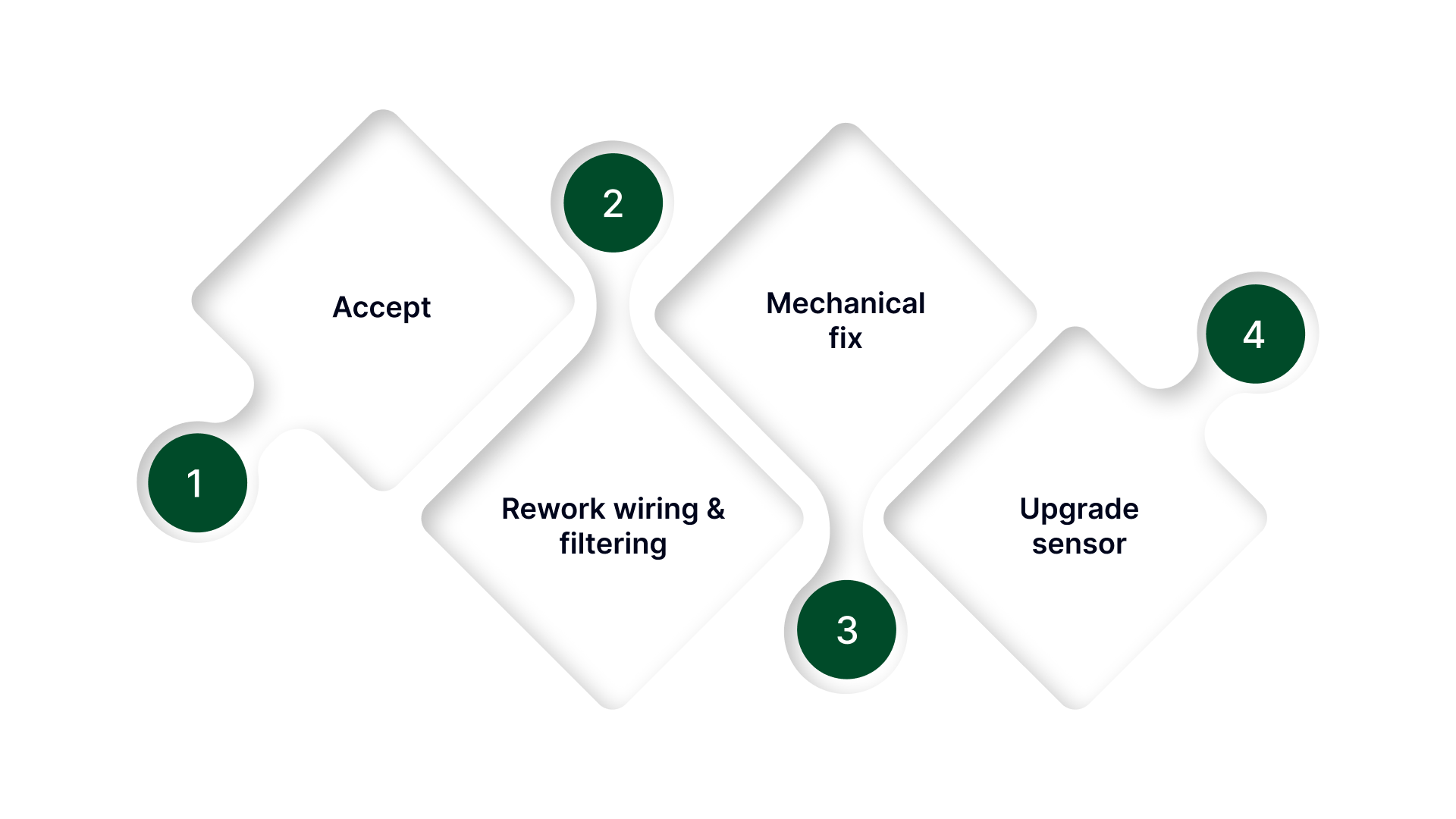
Accept: Repeatability, noise behavior, limit response, and drift all remain within spec under load.
Rework wiring & filtering: Noise is correlated with motor operation, or the signal is unstable at rest.
Mechanical fix: Direction-dependent errors or inconsistent endpoints indicate backlash, coupling issues, or binding.
Upgrade sensor: Persistent wear/noise/drift in the duty cycle or environment makes contact feedback impractical.
If your checklist shows persistent noise, drift, wear, or a need for remote/automatic adjustment of an analog setpoint, it is often more efficient to confirm the right hardware approach than to continue tuning around the limitation.
What On line Controls does
On line Controls supports control and retrofit applications where a potentiometer is used for feedback or for remote adjustment of an analog setpoint.
In the context of the issues covered above, they typically help in the following ways:
Match a motorized potentiometer to your required travel/turns and control approach so scaling, endpoints, and soft limits remain stable.
Reduce damage risk when coupling or limit conditions are not ideal by recommending options that tolerate mechanical mismatch (for example, slip-clutch style protection).
Support retrofit use cases where the requirement is remote setpoint trim (up/down style control) rather than a full controller redesign.
Advise repair/replace when symptoms indicate wiper wear, intermittent output, or non-repeatable feedback.
In addition to selection guidance, application support is available to confirm the most practical approach, and the team can assist with service and repair when troubleshooting points to wear, intermittent output, or repeatability issues.
If you share your current setup and what the checklist revealed (noise, drift, repeatability), On line Controls can help confirm whether the next step is wiring/signal correction, a mechanical fix, or a more suitable feedback/trim hardware specification.
Conclusion
Potentiometer position feedback remains a practical, widely used option when you need a continuous analog indication of position and the application is not pushing extreme accuracy, duty cycle, or environmental limits.
The key is to treat it as a system element sensor, wiring, mechanics, and controller input all contribute to the quality of the result.
If performance is inconsistent, the most useful takeaway is that the signal itself is usually telling you what to do next: instability that correlates with drive operation points to electrical interference and reference integrity, while direction-dependent errors and changing endpoints point to mechanical effects or wear. When those factors cannot be controlled within your requirements, upgrading the feedback method becomes a reliability decision rather than an “optimization.”
With the setup verified and the decision checklist completed, you should have a clear path forward: either proceed with confidence, correct a specific constraint, or select a feedback/retrofit approach better aligned to your operating conditions.
FAQs
Is the potentiometer position feedback absolute?
It is absolute within the sensor’s physical travel as long as the mechanical coupling is fixed. Repeatability can degrade near the end zones or as the track and wiper wear over time.
How do I wire a potentiometer feedback to a PLC analog input?
Use a stable reference supply, ensure the PLC and potentiometer share a proper common/ground, and route the wiper signal away from the motor and PWM wiring. Clamp the scaled value so out-of-range readings do not become control inputs.
Why does potentiometer feedback get noisy when the motor runs?
PWM drive currents and motor leads can couple interference into the signal or ground reference. Correct routing and grounding first, then apply light filtering only as needed to avoid adding excessive lag.
How do I calibrate stroke endpoints?
Move the mechanism to known physical endpoints, record the minimum and maximum raw readings, map the span to engineering units, and set soft limits inside the ends to prevent over-travel and protect the sensor.
When should I choose an encoder instead of a potentiometer?
Choose an encoder when wear, contamination, vibration, high cycle counts, or tight tolerance requirements make a contact-based potentiometer unreliable or too maintenance-intensive.