Introduction
Picture an extrusion operator making constant manual adjustments to line pressure throughout a 12-hour shift. Each twist of a control knob introduces slight variations—sometimes too much pressure, sometimes too little—leading to inconsistent wall thickness, dimensional drift, and operator fatigue by shift's end.
This scenario plays out daily in plastic tubing plants worldwide, costing manufacturers in both product quality and labor efficiency.
Motorized potentiometers eliminate this problem by enabling hands-free, remote setpoint adjustment for industrial processes. These electromechanical devices combine a variable resistor with an electric motor, allowing control systems to automatically adjust critical process parameters like temperature, pressure, and speed without operator intervention.
The result: improved consistency, reduced manual workload, and the ability to integrate legacy analog equipment into modern automated production lines.
This guide covers when motorized potentiometers make sense for your application, step-by-step implementation procedures, and critical performance parameters. You'll also learn integration requirements and common mistakes that turn straightforward installations into troubleshooting nightmares.
Key Takeaways
- Motorized potentiometers combine variable resistors with motors for automated, remote setpoint control
- Best for extrusion lines, mixing systems, and temperature control requiring frequent adjustments or remote operation
- Implementation requires matching resistance ranges, proper motor selection, limit protection, and calibration
- Correct power ratings, current limits, and feedback mechanisms ensure reliable long-term operation
- Alternatives include digital potentiometers (solid-state, no wear) and stepper systems (higher precision, more complexity)
How to Implement Remote Setpoint Control Using Motorized Potentiometers
Step 1: Select the Appropriate Motorized Potentiometer
Determine your control system's input requirements first. Industrial applications typically require resistance ranges from 1kΩ to 100kΩ—values that match standard analog input cards on PLCs and controllers. Vishay's PRV4 industrial series offers standard values including 1k, 2k, 5k, 10k, 25k, 50k, and 100k, covering most industrial control needs.
Match voltage and current ratings to your system:
- Motor voltage: 12 VDC, 24 VDC, or 115 VAC options
- Wiper current: Up to 5 mA (conductive plastic) or 50 mA (wirewound)
- Power rating: 2W typical for industrial use (50% above circuit requirements)
Beyond specifications, configuration depends on your installation space. Rotary models suit panel-mount applications, while linear slide types fit confined spaces.
For long-term reliability, specify conductive plastic elements. These units handle 10-50 million cycles compared to wirewound types rated for only 500,000-2 million turns—critical for applications requiring 10+ year lifespans.

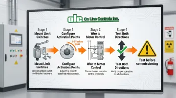
Step 2: Install Limit Switches and Position Feedback
Limit switches prevent serious motor damage from over-travel. Install mechanical or electronic switches at both travel endpoints—these cut power when the potentiometer reaches minimum or maximum positions.
Industrial units often integrate adjustable cam-operated limit switches rated for 4A at 250 VAC, eliminating external wiring complexity. Configure these switches to activate 2-3° before mechanical stops to provide adequate stopping distance.
Position feedback mechanisms include:
- Resistive element feedback: The potentiometer itself acts as a voltage divider
- Dual-gang configuration: One section controls the process; the second provides position feedback to the control system
- Current monitoring: Track motor current to detect end-of-travel stalling
After installation, test both limit switches. Manually rotate the shaft to each extreme and verify the motor stops immediately without forcing against mechanical stops, which causes gear damage and excessive current draw.
Step 3: Integrate with Control System
Wire the potentiometer's resistive element to your control system's analog input. Most industrial systems require signal conditioning:
- 4-20 mA current loops: Preferred for noise immunity over long cable runs; the 4 mA "live zero" also detects broken wires
- 0-10V voltage signals: Common in HVAC but more susceptible to voltage drop and electrical noise
Connect motor control signals to PLC outputs, relay logic, or dedicated motor controllers. For AC motors, you'll need forward/reverse relay contacts. DC motors require polarity reversal circuitry or an H-bridge driver.
Program control logic with manual override capability. Operators must be able to switch between automatic and manual modes during commissioning, troubleshooting, or emergency situations. Implement safety interlocks that prevent simultaneous manual and motorized operation—attempting both causes mechanical binding and gear damage.
Ground cable shields at one end only to prevent ground loops. Add 0.1 µF capacitors across potentiometer terminals to filter high-frequency noise from nearby VFDs or motor starters.
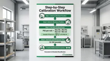
Step 4: Calibrate and Test the System
Drive the motor to minimum position and record the output value displayed by your control system. Repeat at maximum position. Use these two points to define your calibration curve.
For linear applications, calculate the scaling factor: Scaling Factor = (Process Max - Process Min) / (Signal Max - Signal Min)
For example, if your process setpoint ranges from 0-100 PSI and your signal ranges from 4-20 mA: Scaling = (100 - 0) / (20 - 4) = 6.25 PSI per mA
Test response time next. Command the motor to travel full scale. Typical industrial units require 10-160 seconds for full travel, with slower speeds providing better positioning accuracy.
Verify smooth, hysteresis-free operation by commanding the motor to a mid-range position from both directions. The output values should match within your system's resolution. Document everything. Record calibration values and establish recalibration schedules—annually for critical applications, every 2-3 years for non-critical systems.
When Should You Use Motorized Potentiometers for Remote Setpoint Control?
Motorized potentiometers aren't universal solutions. They excel in specific scenarios but are overkill—or the wrong technology entirely—for others.
Ideal use cases include:
- Extrusion line air pressure control: Automatically adjust internal air support pressure as line speed or product dimensions change
- Automated mixing systems: Remotely control motor speeds for ingredient blending from a central control room
- Temperature setpoint adjustment: Modify setpoints across multi-zone heating processes without operators walking to each control panel
- Remote control of inaccessible equipment: Adjust equipment mounted in hazardous areas, at height, or in clean rooms
- Product specification changes: Automatically adjust multiple process parameters when switching between product recipes
When Alternative Technologies Work Better
Choose alternatives when:
- Extremely fast response required: Digital control systems respond in milliseconds; motorized potentiometers need 10-300 seconds for full travel
- Severe vibration present: Solid-state digital potentiometers eliminate mechanical wear in high-vibration environments
- Ultra-high precision needed: Stepper motor systems with encoders deliver superior accuracy and repeatability
- Budget constraints exist: Manual adjustment may be acceptable for low-volume production or infrequent changes
Understanding these use cases and limitations helps you choose the right control method for your process.
The decision ultimately hinges on adjustment frequency. If operators change setpoints more than 5-10 times per shift, automation delivers clear ROI through consistency and reduced labor. For weekly or monthly adjustments, manual control may suffice.
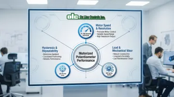
Key Parameters That Affect Performance in Remote Setpoint Control
Three critical parameters determine whether your motorized potentiometer system delivers reliable, accurate control or becomes a source of frustration.
Motor Drive Speed and Resolution
Motor speed determines how quickly setpoints respond to changes. Industrial units typically offer speeds from 10-60 seconds for full travel, though heavy-duty actuators may take 120 seconds for maximum precision.
Resolution—the smallest adjustment increment possible—depends on motor step size and gear ratio.
Conductive plastic potentiometers provide essentially infinite resolution, making them ideal for smooth, continuous adjustments. Wirewound types have distinct steps determined by wire spacing, creating slight "stair-stepping" in the output.
The speed-accuracy tradeoff matters in real applications:
- Faster motors sacrifice positioning accuracy for responsiveness
- Slower speeds improve precision but reduce system reaction time
- Fast-reacting systems need quick motors (10-20 seconds)
- Slow thermal processes benefit from careful adjustment speeds that prevent overshoot
Hysteresis and Repeatability
Hysteresis—the difference in resistance when approaching a position from opposite directions—results from mechanical backlash in gears and slip in the clutch mechanism.
High-quality industrial motorized potentiometers minimize hysteresis through precision mechanics and conductive plastic elements, typically achieving ≤0.25 mm positioning error. This precision matters when control loops depend on exact setpoint values.
Repeatability—returning to the same output value for the same position—is critical for consistent process control.
The system must deliver identical setpoint values across thousands of cycles. Industrial units with conductive plastic elements achieve 0.01 mm repeatability, suitable for precision manufacturing applications.
Load and Mechanical Wear Considerations
Electrical load affects contact life and resistance stability. Wiper current should not exceed 5 mA for conductive plastic elements or 50 mA for wirewound types. Exceeding these limits accelerates wear and causes premature failure.
Mechanical wear factors include:
- Gear backlash: Increases over time, reducing positioning accuracy
- Wiper pressure: Higher pressure improves contact but accelerates resistive element wear
- Resistive element degradation: Shows up as increased rotational torque, linearity errors, and output noise
Select potentiometers with appropriate power ratings for your application's duty cycle. For continuous adjustment applications, specify units with conductive plastic elements rated for 10-50 million cycles rather than wirewound types with 500,000-2 million cycle ratings.
Common Mistakes When Implementing Motorized Potentiometer Control
The most critical oversight is failing to implement limit switches. Without them, the motor stalls at travel endpoints, causing gear damage and excessive current draw as it applies torque against mechanical stops.
Always install adjustable limit switches and test them before commissioning.
Resistance and power rating mismatches create multiple problems:
- Undersized power ratings cause resistive element overheating and accelerated wear
- Oversized resistance values produce insufficient signal strength for your control system's input impedance
- Either mistake results in signal distortion, loading errors, and nonlinearity
Environmental factors often get overlooked during specification. Vibration, temperature extremes, and contamination accelerate wear and cause unexpected failures.
Standard motorized potentiometers may only be rated IP40 or IP50. For washdown areas or harsh environments, specify NEMA 4/4X (IP66) rated enclosures.
Finally, systems without manual override capability leave operators stranded during motor or control system failures. Include a selector switch that disconnects motor control and allows direct manual adjustment of the potentiometer shaft.
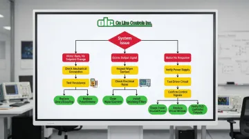
Troubleshooting Issues in Motorized Potentiometer Systems
Even properly designed systems experience issues. Quick diagnosis minimizes downtime and prevents secondary damage.
Motor Runs But Setpoint Doesn't Change
First, check for mechanical disconnection between motor and potentiometer shaft. Common causes include:
- Broken gears in the drive train
- Slipping couplings between components
- Failed clutch mechanisms
Verify by manually rotating the potentiometer shaft while monitoring the output. If resistance changes, the potentiometer works but the mechanical drive has failed.
Alternatively, measure resistance across the potentiometer while operating the motor. If resistance remains constant, the wiper has lost contact with the resistive element due to contamination, wear, or mechanical damage.
Erratic or Noisy Output Signal
When the output signal becomes unstable, start by inspecting the wiper contact. Signs of degradation include increased rotational torque, linearity deterioration, and output noise.
Solutions depend on severity:
- Clean the resistive element if accessible
- Replace the unit if it shows advanced wear
Electrical noise from the motor can also corrupt the analog signal. Motor brush arcing generates high-frequency noise that couples into signal wires.
Reduce noise interference by:
- Adding 0.1 µF filtering capacitors across potentiometer terminals
- Improving grounding connections
- Using shielded twisted-pair cables with shield grounded at controller end only
Motor Doesn't Respond to Control Signals
Power supply issues are a common culprit. Measure voltage at the motor terminals under load—voltage drop indicates inadequate power supply capacity or excessive wire resistance.
Next, test the motor driver circuit or relay. Common failure points include:
- Failed transistors
- Burned relay contacts
- Loose connections
Use a multimeter to verify control signals reach the driver inputs, then check driver outputs reach the motor.
Finally, confirm the control system generates correct signals. Use an oscilloscope to verify pulse width, frequency, and voltage levels match motor controller specifications.
Alternatives to Motorized Potentiometers for Remote Setpoint Control
Digital Potentiometers
Solid-state devices controlled via digital protocols (I²C, SPI) with no moving parts. Resistance changes through electronic switching rather than mechanical wiper movement.
Best applications:
- High-reliability environments with severe vibration
- Microcontroller-based systems requiring programmatic control
- Applications where solid-state reliability outweighs current limitations
Trade-offs to consider:
- Limited current handling: 4.4 mA maximum vs. 50 mA for motorized units
- Lower voltage handling: 2.7-5.5V vs. up to 500V for industrial motorized pots
- Higher cost for equivalent resistance ranges
- No physical position retention—requires power or EEPROM to maintain settings
Stepper Motor with Encoder
Systems using stepper motors with encoder feedback for precise positioning. Encoders offer superior accuracy (±1 grating period) compared to resistive elements.
Choose this approach when you need extremely high positioning accuracy and repeatability, or position memory through power cycles without mechanical retention.
However, expect higher cost and complexity:
- Requires dedicated stepper controller and driver
- Consumes more power than motorized potentiometers
- Needs sophisticated control electronics
This complexity is justified when positioning accuracy exceeds what motorized potentiometers deliver.
Manual Potentiometer with Digital Readout
Traditional manual potentiometers paired with digital position indicators for operator adjustment.
Ideal for:
- Low-volume production with infrequent adjustments (weekly or less)
- Applications where operator involvement supports quality control oversight
- Budget-conscious projects where automation isn't justified
Limitations:
- No remote or automated control capability
- Subject to operator error and inconsistency
- Requires operator presence at adjustment location
This approach offers the lowest cost and simplest implementation.
Conclusion
Motorized potentiometers provide reliable, cost-effective remote setpoint control when properly selected, installed, and maintained. Match potentiometer specifications—resistance range, power rating, motor voltage, and element type—to your specific application requirements for optimal performance.
Critical implementation factors include:
- Proper limit switch protection to prevent motor damage
- Signal conditioning for noise immunity in industrial environments
- Calibration procedures to maintain accuracy over time
When these requirements are met, motorized potentiometers eliminate operator variability and reduce fatigue while enabling integration of legacy analog equipment into modern automated systems.
On Line Controls has manufactured precision motorized potentiometers for over 44 years, serving plastic tubing extrusion and industrial automation applications worldwide. On Line Controls' units combine Japanese-made potentiometers with Swiss DC motors or heavy-duty Hurst AC motors, delivering the 10-20 year operational life that industrial processes demand.
With life expectancies ranging from 500,000 turns for wirewound models to 50 million turns for conductive plastic types, On Line Controls engineers these devices for the continuous operation requirements of demanding manufacturing environments.
Frequently Asked Questions
What is the difference between a motorized potentiometer and a digital potentiometer?
Motorized potentiometers use a physical motor to adjust a resistive element, while digital potentiometers use solid-state switching. Motorized units handle higher power (up to 5W vs. <0.5W), retain position without power, and offer better resolution. Digital units eliminate mechanical wear but require continuous power to maintain settings.
How long do motorized potentiometers typically last in industrial applications?
High-quality industrial units typically last 10-25 years depending on adjustment frequency and environmental conditions. Conductive plastic elements achieve 10-50 million turn life, significantly outlasting wirewound types rated for 500,000-2 million turns.
Can motorized potentiometers be retrofitted to existing control systems?
Yes, they can replace manual potentiometers in most systems with minimal modifications. You'll need motor control circuitry (relays or H-bridge drivers), a motor power supply (12V/24V DC or 115V AC), and control logic programming if using a PLC.
What voltage and current ratings should I look for in a motorized potentiometer?
Match motor voltage to your power supply—12 VDC and 24 VDC are common for industrial applications, while 115 VAC suits stationary installations. Ensure potentiometer power rating exceeds circuit requirements by 50% and wiper current stays below 5 mA for conductive plastic or 50 mA for wirewound elements.
How do I prevent motor wear in frequently adjusted applications?
Use soft-start motor control to reduce mechanical shock, cut power at endpoints with limit switches (avoid continuous holding current), and select units with metal gears. For high-cycle applications, choose conductive plastic elements—they provide 10-50 million turn life vs. 500,000-2 million for wirewound types.
What are the main advantages of motorized potentiometers over manual adjustment?
Key advantages include remote operation from control rooms, automated adjustment based on process conditions, and improved consistency by eliminating operator variability. They also reduce operator fatigue in high-frequency applications and enable integration with automated production systems for recipe-based manufacturing.