Introduction
A motorized potentiometer that's sized wrong for your application doesn't just underperform — it fails. An undersized unit overheats under continuous load; an oversized one wastes panel space and budget while adding no reliability. For controls engineers specifying components in extrusion lines or automated control systems, getting the sizing right the first time matters.
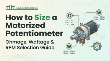
Three parameters drive the sizing decision: ohmage, wattage, and RPM. Each affects a different failure mode — signal resolution, thermal stress, and response time. In continuous-operation environments, unplanned downtime costs manufacturers between $10,000 and $500,000 per hour, making a mispecified potentiometer far more expensive than its purchase price.
This guide walks through how to calculate each parameter correctly — starting with resistance matching, then power dissipation, then motor speed — so you can select a unit that runs reliably for the long term.
Key Takeaways
- Motorized potentiometers combine variable resistance with automated positioning for remote control in industrial applications
- Ohmage sets signal resolution and impedance match; wattage determines how much heat the unit can handle; RPM controls how fast the system responds
- Match your selection to control voltage, load impedance, required adjustment speed, and operating environment
- Properly sized units deliver 10-25 years of reliable operation with minimal maintenance in plastic extrusion and industrial control systems
What is a Motorized Potentiometer?
A motorized potentiometer is a variable resistor with an integrated motor that enables remote, automated, or programmed adjustment of resistance values. Unlike standard potentiometers that require manual adjustment via a control knob, motorized versions allow automated positioning for process control, remote operation, or computer-controlled systems.
The core difference is control capability. Standard potentiometers require physical access, making them practical only for infrequent manual tuning. Motorized versions connect directly with PLCs, SCADA systems, and automated control loops — responding to sensor feedback or programmed sequences without operator intervention.
Core Components of a Motorized Potentiometer
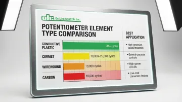
Resistance Element: The resistive material governs durability, noise, and power handling. Four primary types:
- Conductive plastic: Smooth operation, 2,000,000+ cycle life, infinite resolution, low noise
- Wirewound: High power handling, excellent stability (0.01% per 1000 hours), ~10,000 cycle rating
- Cermet: Good stability, 10,000–25,000 cycles, abrasive to wipers
- Carbon: Low cost, poor moisture resistance, significant drift (up to 5% per year)
Motor and Gearbox: The drive mechanism positions the wiper at the required speed and torque. Standard motor voltages run at 4.5 VDC, 6 VDC, 12 VDC, and 24 VDC, with gear ratios from 41:1 to 1670:1 depending on the actuation speed needed.
Position Feedback Mechanism: Advanced models include encoders or limit switches for closed-loop operation. Dual-gang configurations use one potentiometer for control and a second for position feedback. IEC 60947-5-1 recommends independent limit switches with direct opening contacts to prevent over-travel in critical applications.
Mounting Hardware: Panel-mount assemblies integrate the potentiometer, slip clutch, geartrain, and motor in compact packages. The slip clutch protects end stops while allowing manual adjustment when motors are de-energized.
Why Manufacturing Industries Rely on Motorized Potentiometers
Three capabilities make motorized potentiometers the preferred choice in manufacturing environments:
- Remote adjustment — operators change setpoints without accessing live control panels, reducing exposure to hot equipment on extrusion lines and keeping material flow uninterrupted
- PLC integration — gravimetric extrusion systems use motorized potentiometers to adjust screw speed based on loss-in-weight data, holding throughput accuracy within ±0.5%
- Repeatable positioning — units return to preset values consistently across production runs, reducing scrap from recalibration errors over millions of operating cycles

What to Consider When Sizing a Motorized Potentiometer
Proper sizing requires matching both electrical specifications (ohmage, wattage) and mechanical specifications (RPM, torque) to your application. These factors are interdependent: control system voltage and current dictate ohmage and wattage requirements, while process response time determines RPM needs.
Work through electrical requirements first, then mechanical specifications, then confirm environmental compatibility — each step narrows your options before the next begins.
Ohmage (Resistance Value)
Ohmage selection depends on your control circuit's input impedance and the voltage/current levels in your system. The fundamental principle is impedance matching: the potentiometer must present appropriate resistance to both the source and load without distorting the signal or creating excessive loading effects.
The 10x Rule: To maintain output linearity and minimize loading errors, load resistance must be at least 10 times the potentiometer's total resistance. Violating this guideline causes non-linear output voltage curves, particularly at mid-travel positions, leading to control inaccuracies.
Application-Specific Ranges:
- High-impedance circuits (instrumentation, sensor interfaces): 100kΩ-1MΩ minimizes loading on sensitive signal sources
- General control applications (0-10V signals, analog interfaces): 1kΩ-100kΩ balances resolution with manageable power dissipation
- Power control applications (rheostat mode, current trimming): 1Ω-1kΩ handles higher currents while maintaining reasonable physical size
Keep wiper current within limits: excessive current generates noise and accelerates contact wear. Wirewound and cermet types cap out at 100 mA, while precision conductive plastic elements need less than 5 mA for optimal performance.
Wattage (Power Rating)
Wattage rating sets the maximum power the resistance element can safely dissipate. Exceed it and you get insulation breakdown, element deformation, and early failure — so thermal management isn't optional.
Power Calculation: Calculate required wattage using:
- P = I² × R (when current is known)
- P = V² / R (when voltage is known)
Where I is maximum current through the potentiometer and V is maximum voltage across it.
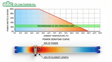
Derating Requirements: Potentiometers are rated for full power at 40°C ambient, with linear derating to zero watts at 125°C. Operate at 20-25% of maximum rated wattage to ensure long life, especially in high-temperature environments like extrusion lines where ambient temperatures may reach 60-70°C.
Power dissipation concentrates unevenly across the element. In rheostat applications, 50% of rated power can be dissipated by just 20% of the resistance element, creating localized hot spots near wiper end positions. Always calculate worst-case scenarios — typically at 50% rotation for voltage divider applications — when determining wattage requirements.
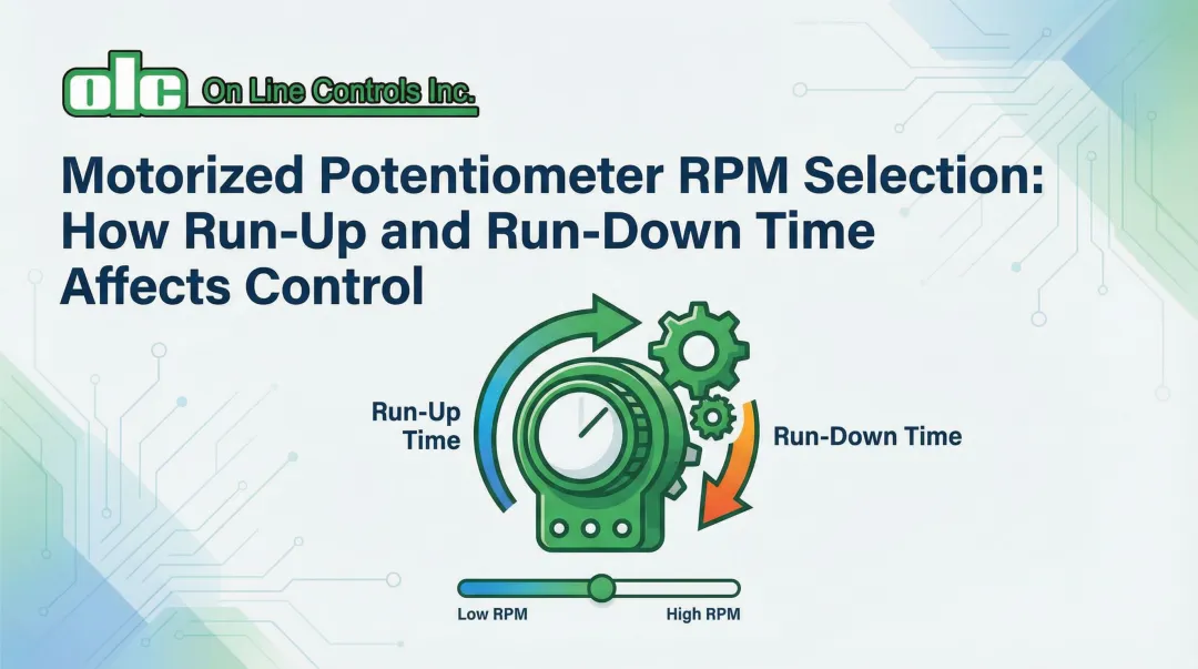
RPM (Motor Speed)
RPM defines the rotational speed of the motor positioning the potentiometer wiper, directly affecting how quickly your system responds to control commands. Speed selection involves balancing response time against control loop stability.
Speed is a trade-off. Higher RPM shortens adjustment time but increases overshoot risk and hunting. Lower RPM gives smoother, more stable positioning with finer resolution — at the cost of slower response.
Calculating Required RPM:
- Determine acceptable adjustment time for your process
- Calculate angular distance the potentiometer must travel
- Divide angular distance by acceptable time to find minimum RPM
- Add 20-30% margin for system variations
Example: For a 10-turn potentiometer (3,600° total travel) requiring adjustment across 50% range (1,800°) within 30 seconds:
- Minimum speed = 1,800° ÷ 30 sec = 60°/sec = 10 RPM
- Recommended specification: 12-15 RPM
Gear ratios from 41:1 to 1670:1 match high-speed DC motors to low-speed potentiometer requirements. Standard ratios like 120:1 suit most applications, while custom ratios optimize performance for specific response characteristics.
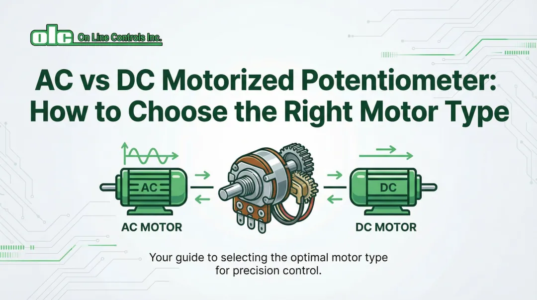
Motor Voltage and Current Requirements
Motor specifications must match your available control system power supply. Common industrial voltages include:
- DC motors: 6 VDC, 12 VDC, 24 VDC
- AC motors: 115 VAC, with limited 24 VAC options available
Current draw affects power supply sizing and wiring requirements. DC motors typically operate at 5-20 mA under normal load, but stall currents may reach 100-200 mA. Size power supplies accordingly, especially in systems with multiple motorized components.
Environmental and Mounting Considerations
Operating Environment: Temperature, humidity, vibration, and contamination dictate material selection and enclosure ratings.
| Environmental Factor | Specification | Impact |
|---|---|---|
| Temperature range | -10°C to +70°C (standard industrial) | Affects derating calculations |
| Humidity | Up to 98% RH for industrial units | Requires sealed housings for reliability |
| Vibration | 2g acceleration, 10-200 Hz | Accelerates mechanical wear |
IP Ratings for Harsh Environments:
- IP54: Protected against dust and water splashing
- IP65: Dust-tight, protected against water jets
- IP67: Dust-tight, protected against temporary immersion
Mounting Orientation: Panel-mount configurations are standard for most industrial applications. Shaft orientation (horizontal vs. vertical) may affect motor torque requirements and lubrication effectiveness in high-cycle applications.
Expected Lifespan and Cycle Life
Cycle life varies dramatically by resistance element type and directly impacts total cost of ownership.
Cycle Life by Element Type:
| Element Type | Typical Cycle Life | Best Applications |
|---|---|---|
| Conductive plastic | 2,000,000+ cycles | High-frequency adjustment, servo feedback |
| Cermet | 10,000-25,000 cycles | Moderate adjustment frequency |
| Wirewound | ~10,000 cycles | Low-frequency adjustment, high power |
| Carbon | ~10,000 cycles | Cost-sensitive, low-performance applications |
Calculating Expected Lifespan:
- Determine adjustments per hour in your application
- Multiply by operating hours per day
- Multiply by operating days per year
- Divide element cycle life by annual cycles
Example: For an application with 10 adjustments/hour, 16 hours/day, 250 days/year:
- Annual cycles = 10 × 16 × 250 = 40,000 cycles
- Conductive plastic lifespan = 2,000,000 ÷ 40,000 = 50 years
- Wirewound lifespan = 10,000 ÷ 40,000 = 0.25 years (3 months)
Factors Extending Operational Life:
- Operating within wattage ratings (proper derating)
- Limiting wiper current to manufacturer specifications
- Appropriate environmental protection (IP-rated enclosures)
- Regular inspection in high-vibration environments
The element type decision — more than any other single factor — determines whether you're replacing a unit every few months or running it for decades. Match the element to your actual cycle demands before finalizing any other specification.
How On Line Controls Can Help
On Line Controls (OLC) has manufactured motorized potentiometers for demanding industrial applications since 2000, backed by over 44 years in manufacturing and process control. OLC serves customers worldwide across plastic tubing extrusion, aerospace, medical equipment, power generation, and maritime applications.
Every unit is built using potentiometers manufactured in Japan, Swiss-made DC motors and geartrains, and heavy-duty Hurst AC motors made in the USA — components chosen for long service life and consistent precision.
Comprehensive Specification Options:
- Resistance: 10Ω to 100kΩ across available models
- Wattage: 0.5W to 5W to match application load requirements
- Motor voltage: 6, 12, or 24 VDC / 115 VAC, all with reversible operation
- Speed: 1 to 120 RPM with custom gear ratios available
- Element type: Conductive plastic (up to 50 million cycles) or wirewound (500,000 to 2 million cycles)
- Configuration: Single-turn or 10-turn; single, dual, or triple gang for feedback systems
Key Benefits:
- Rated for 10–25 years of service life with no calibration required
- Hysteresis-free operation with high linearity across the full range
- Three-year warranty on parts and labor, plus unlimited phone support
- Manufactured in Shrewsbury, Massachusetts with worldwide shipping
- CE compliant for international applications
OLC's technical support team helps you select the right resistance, wattage, RPM, and motor voltage based on your control system's requirements — and every unit is built to order. Contact OLC at 978-562-5353 or olc@onlinecontrols.com for specification assistance.
Conclusion
Getting motorized potentiometer sizing right comes down to matching specifications to what your application actually demands — not defaulting to the highest-rated or priciest component on the shelf.
Start with electrical requirements: calculate load impedance to determine appropriate ohmage using the 10x rule, then calculate worst-case power dissipation and apply proper derating to select wattage. Next, determine mechanical requirements by calculating acceptable response time and selecting RPM accordingly. Then confirm IP rating and temperature range suit your operating environment before committing to a unit.
After installation, monitor performance during initial operation to confirm the unit is behaving as expected. Key commissioning checks include:
- Measuring actual wiper current and verifying power dissipation across the full range of travel
- Conducting thermal checks during full-load operation
- Establishing baseline measurements for resistance linearity and noise
Repeat these checks periodically — catching degradation early prevents unexpected failures down the line.
Frequently Asked Questions
What does 10k mean on a potentiometer?
10k refers to 10,000 ohms (10kΩ) of total resistance between the potentiometer's end terminals. Standard resistance marking conventions use k for thousands (1k = 1,000Ω, 100k = 100,000Ω) and M for millions (1M = 1,000,000Ω).
What wattage rating do I need for my motorized potentiometer?
Calculate maximum power using P = V² / R or P = I² × R based on your circuit's worst-case voltage or current. Select a potentiometer rated for at least 4-5x that calculated value to ensure proper derating and a long service life.
How do I calculate the required RPM for my application?
Determine your acceptable adjustment time, calculate the angular distance the potentiometer must travel (in degrees), and divide that figure by time to find minimum RPM. Add 20-30% margin for system variations. Faster isn't always better: excessive speed causes overshoot and hunting in closed-loop systems.
Can I use a standard potentiometer instead of a motorized one?
Not for automated applications. Standard potentiometers require manual adjustment and can't integrate with PLCs, programmed sequences, or remote setpoint changes. For purely manual, one-time adjustments, a standard pot may suffice.
What happens if I select the wrong ohmage value?
Wrong ohmage creates loading effects if resistance is too low, or poor resolution and control range if it's too high — both cause incompatibility with your system's input impedance. Apply the 10x rule: load impedance should be at least 10 times the potentiometer resistance.
How long do motorized potentiometers typically last in industrial applications?
Properly sized, high-quality motorized potentiometers typically last 10-25+ years in industrial environments. Conductive plastic elements rated for 2,000,000+ cycles cover most high-cycle applications; wirewound elements are better suited to lower-frequency adjustments.