Introduction
In automated control systems, motorized potentiometer RPM (revolutions per minute) directly determines control precision, response time, and system stability. Whether you're managing extrusion processes, valve positioning, or process automation, the rotational speed fundamentally shapes system response.
Engineers face a persistent challenge: balancing speed against accuracy. Set RPM too high, and you introduce overshoot, mechanical stress, and premature component wear. Set it too low, and your system responds sluggishly to process changes, leading to quality issues and wasted materials.
The relationship between RPM selection and run-up/run-down time—the motor's acceleration and deceleration characteristics—is what determines your control performance. This timing affects everything from setpoint accuracy to how quickly your system compensates for disturbances.
This article breaks down how RPM affects control dynamics, what factors influence optimal RPM selection, and how to balance speed requirements against precision constraints in real-world applications.
Key Takeaways
- RPM determines response speed—how quickly the potentiometer reaches target positions
- Run-up and run-down time control overshoot and settling accuracy
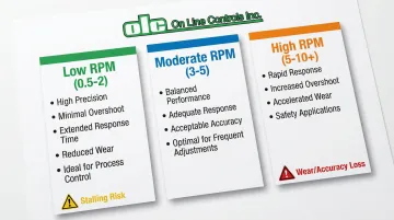
- Lower RPM (0.5-3 RPM) suits precision applications; higher RPM (5-10+ RPM) enables rapid response
- Best selection balances speed needs against mechanical wear and voltage stability
- Frequent adjustments benefit most from moderate RPM (3-5 RPM)
What RPM Represents in Motorized Potentiometers
RPM (Revolutions Per Minute) defines the rotational speed of the motorized potentiometer's drive mechanism—the rate at which the motor and gearbox assembly turns the potentiometer shaft. In precision control applications, this typically ranges from 0.8 to 6 RPM for fine control, though some rapid-response applications require speeds up to 120 RPM.
RPM directly controls response time—how quickly the potentiometer can move through its full resistance range and how fast the controlled system responds to setpoint changes.
The relationship follows a simple formula:
Traverse Time (seconds) = (Number of Turns × 60) ÷ RPM
For a 10-turn potentiometer operating at 2 RPM, full travel requires 300 seconds—limiting control bandwidth to approximately 0.003 Hz.
This mechanical constraint becomes the dominant factor in closed-loop control performance.
RPM serves two roles: as a design parameter (specified by the manufacturer based on motor and gearbox combination) and sometimes as an operating variable. Some designs allow adjustment through supply voltage or PWM control.
Most precision motorized potentiometers use fixed gearing to ensure consistent, repeatable speed characteristics.
Factors That Influence Optimal RPM Selection
Ideal RPM depends on application requirements, not just maximum available speed. Several factors determine the optimal selection:
Application response time requirements: Process control systems typically need slow, stable adjustments (0.5-2 RPM) to prevent oscillation, while safety shutoff applications may require rapid response (5-10 RPM) to meet protection timing requirements
Mechanical load characteristics: Higher inertia loads or friction favor lower RPM to prevent mechanical shock and reduce wear on gear teeth. Repeated high-speed impacts at end stops accelerate component degradation, even with slip clutch protection
Control signal frequency: Systems with frequent setpoint changes experience constant acceleration and deceleration cycles. Operating at very high RPM in these applications dramatically increases wear on the gearbox and motor bearings, potentially reducing service life by 30-40%
Precision requirements: Applications requiring fine positional control (±0.5% or better) typically use lower RPM to minimize overshoot and improve settling accuracy. The kinetic energy of the rotating assembly increases with the square of rotational speed, making precise stopping progressively more difficult at higher RPM
Environmental factors: Temperature extremes, vibration, and duty cycle affect motor performance. Operating temperatures outside the typical -20°C to +66°C range can alter gearbox lubricant viscosity, affecting actual RPM and available torque

Range of RPM in Motorized Potentiometers
RPM is governed by motor design, gearbox ratio, and supply voltage. Most precision motorized potentiometers operate between 0.5 and 10 RPM, with specialized units extending to 120 RPM for rapid-response applications.
Nominal Operating Range
Typical ranges break down by application type:
- High-precision applications: 0.5-1 RPM for maximum positional accuracy
- General-purpose control: 1-3 RPM for balanced performance
- Rapid response/safety applications: 5-10 RPM for faster actuation
These ranges assume standard supply voltage (typically 24VDC or 115/230VAC), normal ambient temperature (0-50°C), and continuous duty rating.
Manufacturer specifications show eight standard DC motor speeds: 1, 3, 5, 10, 18, 35, 61, or 120 RPM, while AC units typically offer 1, 2, 3, 5, 10, or 15 RPM options.
Allowable Tolerance and Boundary Limits
Motor thermal capacity, gearbox mechanical limits, and control stability requirements determine upper limits. Exceeding rated RPM causes several problems:
- Overheating through increased I²R losses in motor windings
- Potential gear tooth damage from excessive loading
- Control oscillation when the system cannot decelerate quickly enough to avoid overshoot
Motor minimum torque requirements and control resolution needs define lower limits. Operating too slowly creates two key problems:
- Insufficient torque to overcome static friction in the potentiometer wiper
- Excessively long response times that render the control system ineffective
For DC motorized potentiometers, RPM is directly proportional to supply voltage. A ±10% voltage variation typically causes ±10-15% RPM variation. Manufacturers commonly specify voltage ranges of 75-125% of nominal, implying wide potential variance if supply regulation is poor.
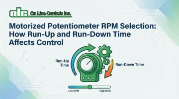
Safe Operating Margin and Run-Up/Run-Down Time Impact
Operating margins exist for critical reasons:
- Handle voltage fluctuations in industrial power supplies
- Account for mechanical wear buildup over years of operation
- Prevent thermal stress during frequent start/stop cycles
Run-up time (time to reach full RPM from stop) and run-down time (time to decelerate to stop) directly affect control performance. Manufacturer specifications indicate coast times as high as 160 ms for unbraked DC motors, which translates to significant overshoot at higher RPM settings.
Longer acceleration times reduce mechanical shock and gear stress but increase response lag. Shorter acceleration enables faster step response but may cause oscillation around the setpoint if the control algorithm cannot compensate for momentum effects.
Consequences of operating at extreme RPM:
- Maximum RPM: Increased overshoot, reduced positional accuracy, accelerated wear on bearings and gears, elevated motor temperature, shortened service life
- Minimum RPM: Potential stalling under load, insufficient control authority, excessively long response times, inability to reject disturbances effectively
Key Technical Properties of RPM Selection
RPM selection involves multiple interrelated properties that collectively determine control system performance. Understanding these relationships is essential for matching the actuator to application requirements.
Property 1: Response Time and Control Bandwidth
The relationship between RPM and system response time follows a straightforward calculation:
Full Travel Time = (Potentiometer Rotation Range ÷ RPM) × 60 seconds
For a 10-turn potentiometer at 3 RPM: (10 ÷ 3) × 60 = 200 seconds for complete traverse. A 10% setpoint change would require approximately 20 seconds of travel time.
Mechanical response time places a hard limit on control loop bandwidth. Industry guidelines suggest actuator response time must be less than 10% of the desired closed-loop time constant to prevent instability.
A motorized potentiometer with 20-second response time suits only control loops with time constants exceeding 200 seconds—very slow processes like large-volume temperature control or gradual pressure adjustments.
An actuator this slow in a fast control loop results in sluggish disturbance rejection and potential instability as the mechanical system cannot keep pace with the controller's demands.
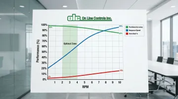
Property 2: Positional Accuracy and Overshoot
Higher RPM increases the kinetic energy of the rotating assembly (KE = ½Iω²), making precise stopping significantly more difficult.
The fundamental trade-off:
- Faster RPM: Reduced response time but increased overshoot and settling time
- Slower RPM: Improved accuracy but extended response time
Manufacturers rarely tabulate specific overshoot percentages, but control theory and experimental data show predictable relationships:
- 1 RPM: Typically <2% overshoot with simple proportional control
- 5 RPM: 5-8% overshoot without derivative action or braking
- 10 RPM: 10-15% overshoot, often requiring dynamic braking
The settling time—how long the system takes to remain within acceptable error bounds—increases with RPM if the system hunts around the setpoint due to coasting. Dynamic braking can significantly reduce coast time, mitigating this effect by converting kinetic energy through electrical resistance rather than mechanical friction alone.
High-precision potentiometers typically feature independent linearity of ±0.25%, but the effective resolution of the motorized assembly depends on the motor's minimum controllable step—a function of RPM, coast time, and control system response.
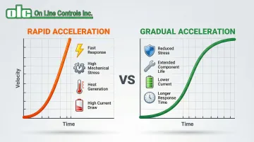
Property 3: Acceleration Profile and Mechanical Stress
Run-up and run-down characteristics create acceleration and deceleration forces that stress mechanical components. Rapid acceleration generates torque spikes that load gear teeth and the motor shaft, while frequent direction reversals during hunting behavior apply maximum stress to the gear train.
DC motors exhibit a linear torque-speed curve where stall torque peaks at zero speed. Rapid starts from stationary apply maximum torque to the gear train immediately, creating the highest stress condition. Frequent start/stop cycles at high RPM dramatically increase wear.
Thermal generation compounds mechanical stress. Acceleration draws high inrush currents (up to the stall current limit), causing rapid heating of motor windings. If the duty cycle exceeds the motor's rating—often based on continuous operation at nominal torque—thermal protection or derating becomes necessary.
The trade-offs become evident:
- Rapid acceleration: Fast response, high gear stress, increased power consumption, elevated thermal generation
- Gradual acceleration: Reduced mechanical stress, lower peak current, extended component life, longer response time
How RPM Is Specified, Measured, and Validated
RPM functions as both a design specification (what the manufacturer guarantees) and an operational parameter (what can be verified in the field). Understanding both aspects ensures proper system design and troubleshooting.
Specification and Documentation
Datasheets typically list RPM as nominal RPM at rated voltage, with a tolerance range of ±10-20%. Test conditions should reference specific voltage, ambient temperature, and load conditions, though not all manufacturers provide complete details.
A critical distinction exists between no-load RPM (maximum theoretical speed with no resistance) and loaded RPM (actual operating speed under typical resistance). The difference can be considerable, particularly for lower-power motors where internal friction and potentiometer wiper resistance represent significant loads.
Measurement and Verification Methods
Practical measurement approaches include:
- Optical tachometers: Non-contact sensors using reflective tape, suitable for 1-250,000 RPM range with high accuracy
- Stopwatch timing: For very low speeds (<1 RPM), timing multiple complete rotations provides accurate average RPM
- Encoder feedback: Continuous monitoring for closed-loop applications requiring real-time speed verification
These measurement methods reveal important differences between field and lab conditions. Ambient temperature affects copper winding resistance (approximately 0.4% per °C), altering motor current and speed characteristics.
Supply voltage stability, mechanical load variations, and bearing friction changes over time all affect measured RPM in field conditions compared to factory specifications.
Simple field verification:
- Mark the output shaft with tape or marker
- Time multiple complete rotations with a stopwatch
- Calculate: RPM = (Number of Rotations ÷ Time in Minutes)
- Compare against datasheet specs, accounting for voltage and load
Implications of Operating Outside the Recommended RPM Range
Operating beyond specified RPM limits triggers predictable wear patterns that compromise performance and shorten service life.
Performance Loss Mechanisms
Operating above rated RPM reduces positional accuracy through increased overshoot, creates control instability through insufficient deceleration time, and decreases repeatability due to momentum effects. The system may exhibit hunting behavior—continuously overshooting the target and reversing direction in a limit cycle that prevents stable operation.
Operating below minimum RPM causes slow control response, making the system unable to reject disturbances effectively. The motor may stall repeatedly if available torque drops below the level needed to overcome static friction in the potentiometer wiper and gearbox.
Accelerated Wear and Failure Modes
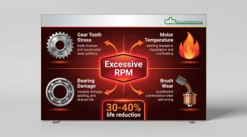
Excessive RPM accelerates multiple failure modes:
- Gear tooth stress: High-speed operation increases contact forces, leading to premature gearbox failure through tooth fracture or excessive wear
- Motor temperature: Higher speeds increase I²R losses and reduce cooling effectiveness, degrading winding insulation and shortening motor life
- Bearing damage: Increased vibration at high speeds causes bearing race damage and eventual seizure
- Brush wear: For brushed DC motors, commutation frequency increases with speed, accelerating brush wear
These wear patterns combine to reduce component life significantly. Operating at 50% above rated speed can reduce expected service life by 30-40%, with specific impacts varying by design.
System-Level Impacts
Beyond component-level failures, improper RPM selection creates system-wide problems.
Insufficient RPM makes the control loop unable to respond to process disturbances within acceptable timeframes, allowing quality deviations or unsafe conditions to persist. Excessive RPM creates instability where the controller continuously overshoots, causing process variability, increased reject rates, and potential equipment damage from oscillating loads.
Common Misinterpretations of RPM in Motorized Potentiometer Selection
Three misconceptions frequently derail motorized potentiometer performance, costing engineers time and precision in extrusion control applications:
"Faster is always better" represents the most common error. While higher RPM improves response time, it sacrifices positional accuracy, increases mechanical wear, and may cause control instability in applications requiring precision.
A 10 RPM motor that overshoots by 15% and requires 5 seconds to settle delivers worse effective performance than a 3 RPM motor that reaches the target smoothly in 8 seconds.
Engineers who ignore run-up and run-down time effects while focusing only on steady-state RPM encounter overshoot and settling time issues that weren't apparent in initial calculations. The 160 ms coast time in a typical DC motor may seem negligible, but at 10 RPM it translates to approximately 1° of additional travel—potentially significant in high-resolution applications.
Catalog specifications rarely match field conditions without accounting for real-world variables. Voltage variations of ±10% are common in industrial environments, directly affecting DC motor speed.
Temperature effects, mechanical load differences from installation variations, and accumulated wear over years of operation all cause actual RPM to deviate from catalog values.
Conclusion
RPM fundamentally determines the balance between response speed and control precision in motorized potentiometer applications. Rather than maximizing RPM, select values that align with process dynamics, precision requirements, and mechanical constraints.
Understanding the interplay between RPM, run-up/run-down time, and application requirements is essential for selecting the right motorized potentiometer.
Key selection considerations include:
- Precision applications: Lower RPM provides superior positional accuracy and stable control
- Fast-process applications: Higher RPM enables rapid response in safety-critical systems where speed takes priority
- Application matching: Balance response speed against the mechanical and electrical constraints of your specific system
Engineering judgment in matching RPM characteristics to specific application demands matters as much as published specifications. Optimal performance comes from system design that considers control bandwidth requirements, mechanical load characteristics, environmental conditions, and long-term reliability.
Frequently Asked Questions
Can L298N control speed?
Yes, the L298N is a dual full-bridge motor driver IC that controls DC motor speed through PWM signals. It drives the DC motor within a motorized potentiometer assembly rather than controlling the potentiometer directly. Its 46V voltage rating and 4A current capacity accommodate most motorized potentiometer motors.
What is the typical RPM range for motorized potentiometers used in process control?
Most process control applications use 0.5 to 3 RPM to balance response speed with positional accuracy. This range prevents oscillation while providing adequate control for gradual adjustments in temperature, pressure, and flow systems.
How does run-up time affect control system stability?
Longer run-up time improves stability by limiting acceleration momentum, but it slows response. Shorter run-up time enables faster response but may cause oscillation if the controller can't compensate. The optimal balance depends on your specific process characteristics.
Can I increase RPM by increasing supply voltage to my motorized potentiometer?
While RPM increases with supply voltage, exceeding rated voltage risks overheating, insulation breakdown, and premature failure. This also voids warranties and damages components. Always consult manufacturer specifications before adjusting voltage.
What RPM should I choose for an application with frequent setpoint changes?
Moderate RPM (2-4 RPM) balances response speed with mechanical longevity in applications with frequent setpoint changes. Constant acceleration and deceleration cycles at high RPM significantly increase wear on the gearbox and motor bearings, potentially reducing service life by 30-40%. Lower speeds extend component life while still providing adequate response for most industrial processes.
How do I measure the actual RPM of my motorized potentiometer in the field?
Mark the shaft with tape, time 5-10 complete rotations with a stopwatch, then calculate RPM = (Rotations ÷ Time in Minutes). Compare against datasheet specs, accounting for supply voltage and temperature. For speeds below 1 RPM, time 10+ rotations for better accuracy.