Introduction
When a motorized potentiometer reaches its mechanical limit without protection, the results are immediate and costly: stripped gears, burnt-out motors drawing excessive stall current, and broken mechanical stops. For industries like plastic extrusion, robotics, and aerospace that depend on precision analog control, a single failure can halt production and require expensive component replacement.
The slip clutch is a critical but often overlooked internal component that prevents this damage. This mechanical safety feature protects against catastrophic failure during end-of-travel conditions, manual overrides, or calibration drift.
Without this protection, motors can draw excessive stall currents, strip plastic gears, or break mechanical stops entirely. The slip clutch disengages when torque exceeds safe limits, allowing the motor to continue rotating harmlessly.
This guide explains what a slip clutch is, how it functions within a motorized potentiometer, why it's essential for reliability, and where it provides the most value in industrial and precision control applications.
Key Takeaways
- Slip clutches enable controlled slippage when torque exceeds preset thresholds (20-60 mN·m industrial, 150-450 g·cm precision)
- Protects mechanical stops, gears, and resistive elements by allowing motor to idle at travel limits
- Enables safe manual override without damaging the motor, extending component lifespan and reducing maintenance costs
- Critical for industrial actuators, process control, medical equipment, and aerospace applications
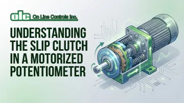
What Is a Slip Clutch in a Motorized Potentiometer?
A slip clutch is a torque-limiting mechanical coupling device integrated between the motor's gear train and the potentiometer shaft. It disengages (slips) when rotational force exceeds a calibrated threshold, typically measured in gram-centimeters or Newton-meters.
The Operational Gap It Fills
Motorized potentiometers combine precision positioning with the risk of over-travel damage when automated systems push beyond mechanical stops or equipment goes out of calibration. The slip clutch acts as a protective safety mechanism that yields before expensive components break.
Real-world protection scenarios:
- Motor receives faulty command to continue rotation past physical limit
- User manually overrides motor by turning shaft during operation
- Calibration drift causes system to drive against end stops repeatedly
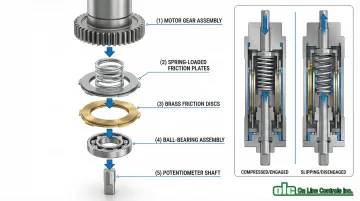
Physical Construction
Slip clutches in motorized potentiometers typically consist of:
- Spring-loaded friction plates or brass discs sandwiched between the final drive gear and potentiometer shaft
- Ball-bearing assemblies (stainless steel in aerospace applications) for smooth operation under side loads
- Adjustable spring tension controlling the slip torque point
Friction surfaces are selected to prevent excessive wear during prolonged slip events. Materials maintain consistent friction characteristics across temperature ranges.
What a Slip Clutch Is NOT
Clarifying common misconceptions:
- Not an electronic limit switch (operates purely mechanically)
- Not a soft-start circuit (no electrical components)
- Not a feedback sensor (requires no programming)
- Not a resettable circuit breaker (re-engages automatically)
Manufacturer Integration
Understanding how slip clutches prevent damage explains why manufacturers design them into specific product lines.
Bourns, P3 America, and OLC integrate slip clutches into motorized potentiometers for mechanized systems like linear actuators, cable transducers, and process control valves. In these applications, occasional over-rotation is expected during normal operation.
| Manufacturer | Model | Slip Torque Range | Application Focus |
|---|---|---|---|
| Bourns | PRM16 | 150-450 g·cm | Precision audio/instrumentation |
| P3 America | MT22IR | 20-60 mN·m | Industrial feedback devices |
| OLC | MC/MAC Series | Factory-set (proprietary) | Plastic extrusion control |
OLC's motorized potentiometers include factory-calibrated slip clutches across all models, with the company emphasizing that field adjustments will void warranty coverage due to the precision required for proper protection.
How Does a Slip Clutch Work in a Motorized Potentiometer?
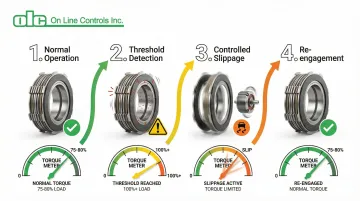
A slip clutch operates through a defined mechanical sequence: normal torque transmission during standard operation, threshold detection when force exceeds the preset limit, controlled slippage to dissipate excess torque, and automatic re-engagement once conditions normalize.
Normal Operation
During standard operation, the motor drives the gear reduction assembly which transmits torque through the slip clutch to rotate the potentiometer shaft.
The spring-loaded friction surfaces remain locked together by clamping force, transferring 100% of motor torque to the wiper arm for precise positioning.
Slip initiation occurs when:
- Potentiometer reaches mechanical stop (end of travel)
- User manually overrides motor by turning shaft
- Motor receives faulty command to continue rotation beyond physical limit
In each case, resistance torque exceeds the clutch's calibrated slip threshold.
Slippage Mechanism
When applied torque exceeds the spring preload holding friction plates together, the clutch surfaces begin to slide relative to each other.
The motor continues to spin its output gear, but the potentiometer shaft remains stationary or rotates at a reduced rate.
Key operational characteristics:
- Typical torque ratings: 150-450 g·cm for audio models, 20-60 mN·m for industrial variants
- Friction surfaces dissipate excess mechanical energy as heat
- Motor current remains at normal levels (no stall current spike)
- Prevents buildup of destructive forces that would shear gear teeth or crack housing
The running torque of a precision potentiometer is typically 75-80% of its starting torque, requiring the clutch to maintain a delicate balance between driving the load and slipping safely at the stops.
Calibrated Torque Thresholds
This precise slippage action depends on careful calibration. The slip clutch maintains system safety under varying conditions through calibrated spring tension that must be:
- High enough to overcome friction in the resistive track and gear train
- Low enough to yield before mechanical stops fail
Why calibration prevents cascading failures:
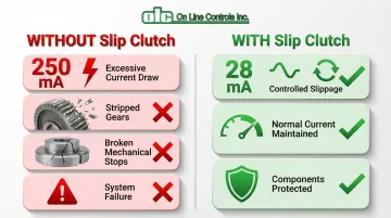
Without a slip clutch, a motor driving against a hard stop can:
- Draw excessive current (up to 250 mA vs. 28 mA normal), burning out windings
- Strip plastic or brass gears when torque exceeds material strength
- Break mechanical stops (rated for 4 in-lb / 0.45 Nm maximum)
- Cause positional accuracy loss, electrical shorts, or system failure
Re-engagement and Manual Override
Once the over-torque condition is removed—motor command stops, user releases manual override, or system resets—the spring force re-engages the friction surfaces. Normal motorized operation resumes without manual intervention or recalibration.
Integration into control systems:
- Control loop detects end-of-travel via position feedback (wiper voltage)
- System issues corrective commands without triggering alarms
- No maintenance required after slip event
- Operators can manually adjust settings by hand without damaging motor or disengaging power
- Control returns to automation seamlessly
Where Slip Clutches Are Used in Motorized Potentiometers
Industrial Process Control
Motorized potentiometers function as setpoint adjusters in demanding industrial applications—valve positioners, flow controllers, and speed regulators. Slip clutches protect these systems from mechanical failure during both automated operation and manual intervention.
Specific applications:
- Plastic extrusion systems: OLC's motorized potentiometers control tubing diameter through precise air pressure regulation, where equipment runs continuously for months and calibration drift is inevitable
- Chemical processing: Valve position control where pressure differentials can twist actuator shafts
- Power generation: Speed reference controls for turbine systems
Continuous operation in these environments creates two failure risks: automated over-travel from sensor drift and mechanical stress during manual process adjustments. Slip clutches eliminate both.

Medical and Laboratory Equipment
Medical devices demand fail-safe design. Motorized potentiometers with slip clutches adjust pump speeds, actuator positions, and sensor calibration while tolerating both automated control and manual emergency overrides.
Critical benefits:
- Patient safety through fail-safe design
- Reduced service interruptions in critical care equipment
- Compliance with medical device reliability standards
- Zero-maintenance operation in sealed environments
Aerospace and Defense
Aerospace applications specify slip clutch-equipped potentiometers for control surfaces, simulator throttle quadrants, and instrumentation. High-vibration, extreme-temperature environments demand mechanical robustness without compromise.
Documented implementations:
- Flight simulator throttle quadrants: Boeing 737 simulator retrofits replaced clutch-less designs that caused binding and jerky movement with slipper clutch assemblies, achieving smooth operation and zero maintenance
- Aircraft instrumentation: Position feedback systems in closed-loop control applications
- Control surface actuators: High-reliability units rated for 1 million rotational cycles
Standards compliance:
- MIL-PRF-19: Military specification for variable resistors mandating stop torque protection
- RTCA DO-160 Section 8: Vibration resistance requirements for airborne equipment (slip clutches isolate potentiometer element from shock loads)
- US Army Corps EM 1110-2-2610: Recommends slip clutches rated for 200% of maximum calculated torque in gate operating mechanisms

Conclusion
The slip clutch transforms a motorized potentiometer from a precision positioning device into a robust, fault-tolerant component capable of surviving real-world operational stresses.
This simple mechanical safeguard protects both the potentiometer and motor from damage due to over-travel, manual overrides, or system errors—preventing failures that would otherwise require complete component replacement.
Understanding slip clutch function helps you:
- Specify motorized potentiometers with appropriate torque ratings for your application
- Recognize when slippage indicates a need for recalibration
- Reduce total cost of ownership through extended component life and minimized downtime
With industrial adoption exceeding 61% of control panels and lifecycle ratings reaching 1 million rotational cycles, slip clutches have become a proven standard for reliability in automation systems worldwide.
Frequently Asked Questions
How does a slip clutch work?
A slip clutch uses spring-loaded friction surfaces that remain locked under normal torque, transmitting power from motor to shaft. When torque exceeds the preset threshold, the surfaces slip relative to each other—allowing the motor to rotate harmlessly while the shaft stays stationary—then re-engage automatically once the overload is removed.
Can a potentiometer control a motor?
A standard potentiometer outputs a variable signal used as input to a motor controller, but doesn't directly control motor power. In a motorized potentiometer, the motor adjusts the potentiometer's position, and a slip clutch allows manual adjustment without back-driving or damaging the motor.
What happens if a motorized potentiometer operates without a slip clutch?
Without a slip clutch, driving the motor into a mechanical stop can strip gears, break internal stops, or burn out motor windings from stall current (250 mA vs. 28 mA normal). This leads to costly failures, lost positional accuracy, and complete component replacement.
How do you adjust the slip torque on a motorized potentiometer's clutch?
Slip torque is typically factory-set using calibrated spring tension. Some industrial models support field adjustment via tension nuts, but many precision units are factory-sealed. Consult the manufacturer's datasheet, as incorrect settings can either allow unwanted slippage or fail to protect against damage.
Why would a slip clutch engage during normal operation?
Premature slippage suggests the clutch torque setting is too low for the load, excessive friction in the wiper or gear train, or mechanical binding from contamination or wear. Inspect to verify torque calibration, clean or lubricate moving parts, and check for damaged gears or misalignment.
Are slip clutches in motorized potentiometers maintenance-free?
Slip clutches are designed for long-term, low-maintenance operation (often millions of cycles), but periodic inspection is recommended in high-duty applications. Check for friction surface wear, verify spring tension, and ensure no debris contamination. Manufacturers like OLC specify maintenance intervals in their technical documentation.