Rheostat switches show up in motor retrofits for one reason: they are simple. You get a knob, a series resistance path, and a quick way to limit top-end output without reworking the rest of the machine.
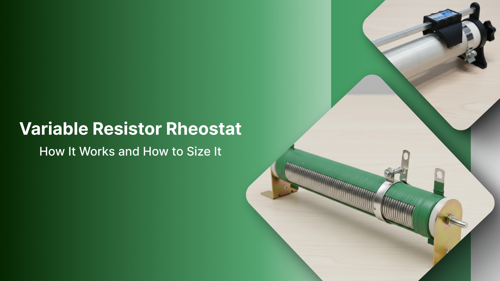
But a rheostat is not a motor controller. It is a power resistor. It slows a motor by dropping the voltage under load and converting the unused power into heat.
When it’s misapplied or sized and mounted like a low-power control device, you get the same failures every time: speed that won’t hold under load, overheated insulation, drifting settings, and repeat replacements that never last.
This guide is built for retrofit and reliability work in real panels. It covers application fit (where a rheostat switch helps vs. where it guarantees drift), series wiring and switching practices that avoid common failure modes, mechanical and thermal sizing so the unit survives the duty cycle, and a short under-load acceptance check to confirm the installation is production-ready.
Key Takeaways
Wire it in series with the motor load path (rheostat = series resistance). It is not a control signal device.
Select for heat first: watts, duty cycle, and enclosure airflow/ambient. Ohms alone are how installs fail.
For repeatable speed under changing load, don’t use a rheostat: use PWM (DC) or a VFD (AC/3-phase).
Accept/reject under load: smooth adjustment, no dropouts/jumps, and a stable temperature rise at normal duty.
Mounting matters: secure anti-rotation, strain relief on terminals, and clearance so terminals aren’t stressed when the door moves.
Is a rheostat switch the right control for your motor?
Before you wire anything, confirm you are solving the right problem. A rheostat switch is not a “speed controller.” It is a series resistance device that reduces the voltage available to the motor under load, and it does that by dissipating power as heat. In other words, it can be useful for coarse limiting. It is rarely the right tool for repeatable speed.
Start with the control goal
A rheostat switch is typically a fit when the goal is one of these:
Cap the top end (reduce maximum speed/power in a simple way)
Coarse trim for a legacy setup where efficiency and tight regulation are not required
Temporary limiting during setup or test conditions
If your goal is set-and-hold speed across changing load, a rheostat will fight you. The speed will move because the voltage drop changes with current.
Motor fit check: where a rheostat switch is realistic
Use this as a fast filter:
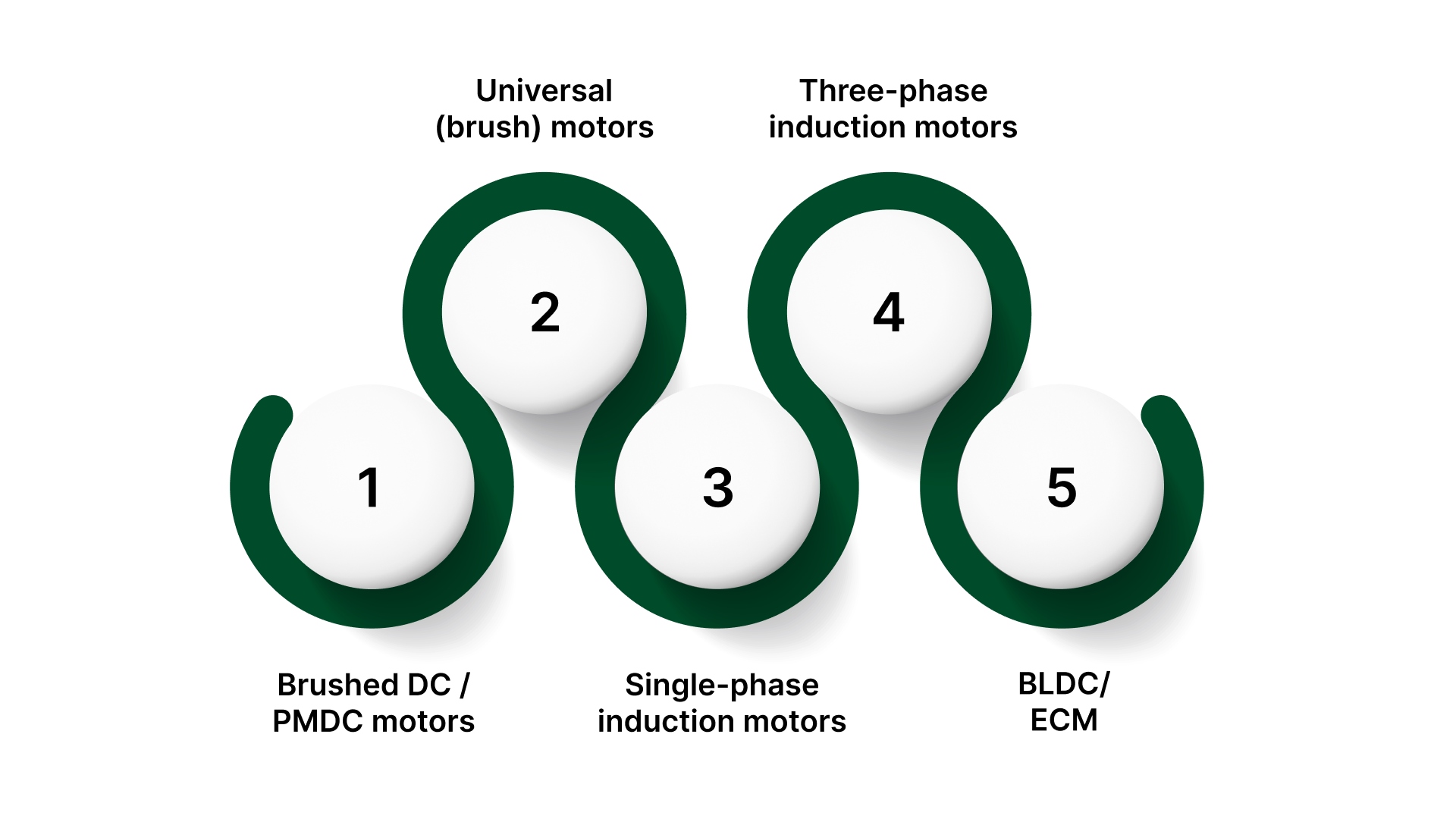
Brushed DC / PMDC motors: Sometimes workable. You can reduce speed/torque by dropping voltage, but performance will be load-dependent, and the rheostat must be sized for heat.
Universal (brush) motors: Usually not ideal. These are typically controlled with purpose-built electronic controls; resistive control wastes power and can be inconsistent.
Single-phase induction motors: Not a proper speed control method. Expect weak torque and unstable behavior under load.
Three-phase induction motors: No. Use a VFD if speed control is required.
BLDC/ECM: No. These expect a controller input; series resistance is not a valid control strategy.
Load reality: why “it worked on the bench” fails in production
A rheostat “slows” the motor by dropping voltage, but the drop is tied to current:
As the load increases, motor current rises.
The voltage drop across the rheostat increases.
The motor loses voltage and torque sooner, so speed falls more than expected.
This is why a setting that looks stable at idle can become unstable once the process is doing real work.
What “rheostat switch” usually mean in the field
People use the term in two different ways:
A switch plus a rheostat in the motor power path (on/off and a series adjustment)
A “knob” that sets a controller input (potentiometer/setpoint into a drive)
Only the first case is a true rheostat application. If the existing system already has a drive or controller input, the correct fix is usually a potentiometer/setpoint solution, not adding series resistance.
Red flags that mean “don’t use a rheostat.”
If any of these are true, a rheostat switch is usually the wrong approach:
The process needs a repeatable speed under varying loads
The motor must maintain high torque or avoid stalling
Operators are already “chasing the knob” to hold output
The application runs a continuous duty where heat dissipation will be constant
A stall or speed drop creates a safety or quality risk
If this section says it’s a fit, the next step is wiring it in series correctly, specifically, wiring and switching practices that avoid the common failure modes: overheated terminals, unsafe switching, and installations that drift under load.
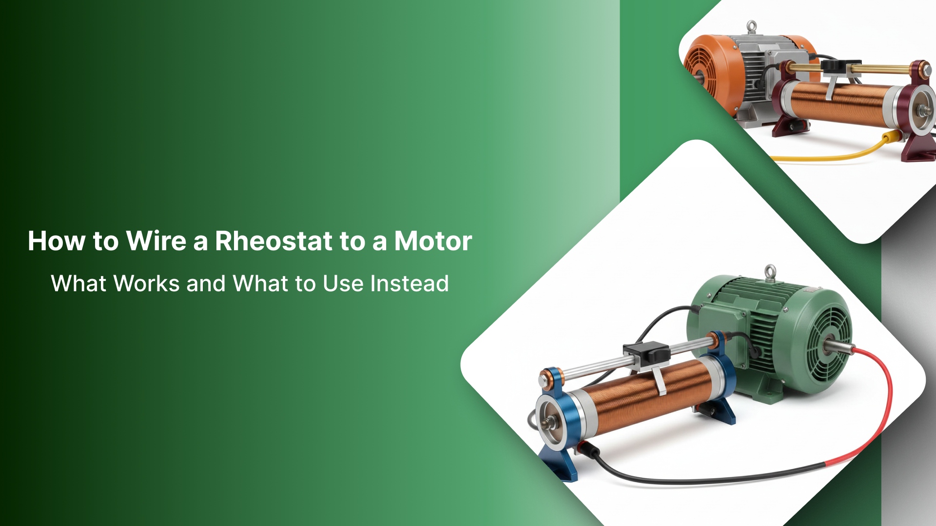
How to wire a rheostat switch to an electric motor
A rheostat “switch” installation fails for two reasons: it’s wired in the wrong place (parallel or on the wiper), or the switch path is asked to interrupt current it was never built to handle.
The goal here is simple: put the rheostat in the motor current path, and switch the supply with a properly rated device.
Core rule: the rheostat is a series device
A rheostat is used as a 2-terminal variable resistor (the wiper + one end of the resistive element).
It must be in series with the motor so all motor current flows through it.
Do not wire it like a control signal, and do not wire it in parallel expecting a “voltage trim.”
The basic series pattern (DC motors)
Use this as the baseline field pattern for brushed DC/PMDC applications:
Supply (+) → fuse/breaker → switch/contactor → rheostat (2-terminal) → motor (+)
Motor (–) → supply return (–)
Notes that prevent common rework:
Put the protective device (fuse/breaker) upstream.
Put the switch upstream so you are switching supply current, not trying to “switch the resistor.”
If it’s a combo unit (rheostat + switch): identify terminals correctly
Combo units vary, but the practical identification method is consistent:
The switch terminals will usually be a separate pair (often marked line/load, or isolated from the resistive element).
The rheostat terminals will include:
Wiper (variable output point)
End terminal(s) of the resistive element
How to confirm before energizing:
With power isolated, use a meter to find the resistive element (you’ll read resistance between end terminals; the wiper-to-end value changes with rotation).
Keep the switch function separate: the switch should open/close the supply path, not “pick off” a point on the resistive element.
Switching guidance that avoids arcing and burnt tracks
Switch the supply (line), not the wiper.
Avoid any arrangement where the switch interrupts at the wiper contact. That increases arcing risk and accelerates wiper/track damage.
If the load is inductive (motors are), expect higher stress at opening. Use a switch/contactor rated for the voltage and current type (DC switching is especially demanding).
Protection basics (why “good connections” matter as much as wiring order)
Size the fuse/breaker to the circuit and motor characteristics, per your site standard and motor documentation.
Treat every termination as a potential heater:
Loose lugs, undersized wire, and poor crimps turn into resistive heat under current.
Heat at terminals often gets blamed on the rheostat, but it’s usually a connection problem first.
Safety requirements
Apply lockout/tagout and verify zero energy.
Follow site standards for wire type, insulation temperature rating, grounding/bonding, and enclosure routing.
Before energizing, verify with a meter:
Correct series path continuity
No shorts to ground/chassis
Expected resistance change as the knob rotates (with the circuit de-energized)
Correct wiring is only half the job. Most repeat failures happen because the rheostat is under-rated for heat, or mounted where heat cannot escape—so the next step is sizing and mounting it for the real duty cycle.
How to size and mount it so it survives
Most “rheostat switch” installs don’t die because the wiring is wrong. They die because the part is asked to dissipate real power continuously inside a warm enclosure with poor airflow. If you size and mount for heat first, everything else gets easier.
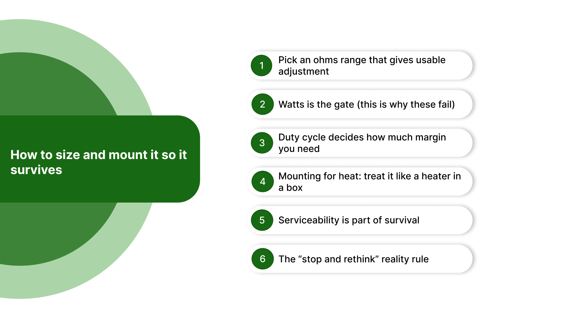
1) Pick an ohms range that gives usable adjustment
The right resistance value is the one that spreads control across the knob travel where the motor actually runs.
If the motor goes from “barely turns” to “near full speed” in a small part of rotation, the range is mismatched.
A better match gives you:
Smooth change across travel
A stable “working zone” you can return to
Less temptation to run at extreme settings where the heat is worst
Practical check: if operators live in the last 10–15% of knob travel, the resistance range is usually too high (or the application wants a controller, not a resistor).
2) Watts is the gate (this is why these fail)
A rheostat slows/limits by dropping voltage under load. The “missing” power becomes heat in the rheostat.
Higher current = higher dissipation
More voltage dropped across the rheostat = more dissipation
Heat is not a fault condition. It’s the operating principle.
Field reality: you can match the ohms perfectly and still cook the install if the watt rating (and real cooling) aren’t there.
3) Duty cycle decides how much margin you need
Two installs with the same motor current can have totally different survival odds:
Set up trim/occasional adjustment: short periods of dissipation, time to cool
Continuous operation: steady dissipation for hours → you need major thermal headroom
If the rheostat is expected to run warm as “normal,” spec it like a continuous-duty heater component, not like a panel knob.
4) Mounting for heat: treat it like a heater in a box
Mounting isn’t cosmetic. It determines whether heat can leave the part.
Avoid dead-air pockets: don’t bury it behind wire duct, tight bundles, or back-to-back devices
Keep separation from wiring and plastics: don’t route wiring over the rheostat body or terminals
Use chassis mass when dissipation is meaningful: chassis mounting or a substantial metal mounting surface often survives better than a thin panel-only install
Don’t stack heat sources: keep away from drives, contactors, transformers, heaters, and hot air rise paths
Rule: if you wouldn’t mount a power resistor there, don’t mount a rheostat there.
5) Serviceability is part of survival
If techs can’t access it cleanly, it turns into a failure later.
Leave clearance for:
Terminal lugs and bend radius
Tool access for tightening
Visual inspection for discoloration or insulation damage
Add strain relief so vibration or door movement cannot load the terminals
A good installation should not rely on terminals to carry mechanical forces.
6) The “stop and rethink” reality rule
If the rheostat must run hot all day to achieve the required motor behavior, you are using it as a continuous power dump.
At that point, the better fix is usually:
PWM for brushed DC/PMDC motors, or
VFD for AC/3-phase induction motors
Upsizing resistors forever is how plants end up with repeated failures and hot enclosures.
If the install “works” but won’t hold speed or it runs too hot under normal duty, the right move is often changing the control method, not chasing bigger rheostats.
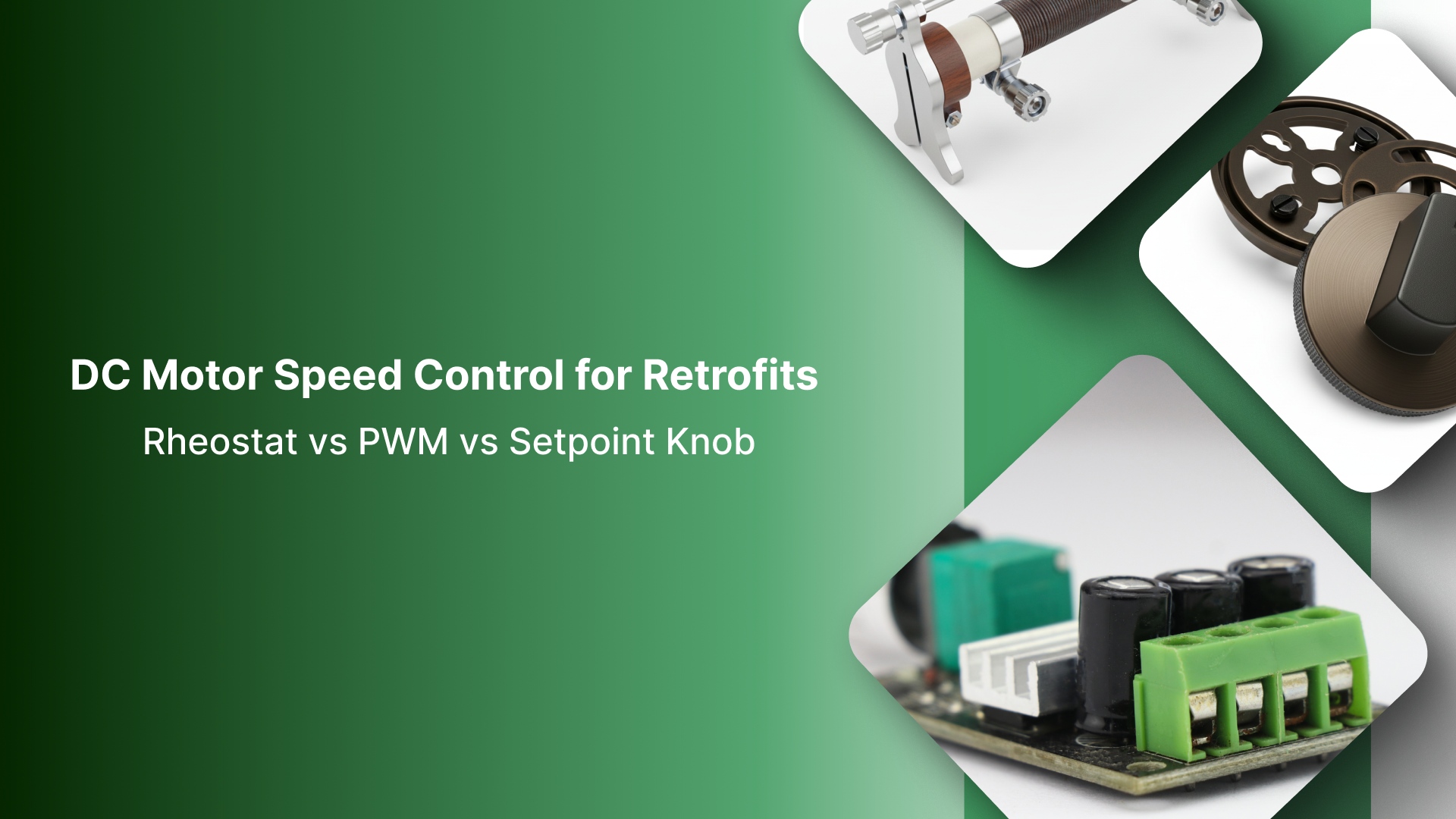
Rheostat vs PWM vs VFD
When a team asks for a “rheostat switch for an electric motor,” they usually want one of two outcomes:
A simple limiter/trim (acceptable that speed shifts with load)
A set-and-hold speed control (repeatable and stable under load)
A rheostat can sometimes do the first. It rarely delivers the second.
Quick comparison
Field | Rheostat (series resistance) | PWM DC speed controller | VFD (Variable Frequency Drive) |
|---|---|---|---|
What it really controls | Voltage drop under load (not regulation) | Average motor voltage electronically (efficient) | Motor frequency/voltage profile (true speed control) |
Best fit motor types | Brushed DC / PMDC (limited cases) | Brushed DC / PMDC | AC induction (especially 3-phase) |
What you get | Simple “cap” or coarse trim; cheap retrofit | Repeatable speed control; better torque retention; low heat waste | Controlled speed, ramps, protection features, repeatability |
Primary trade-off/risk | Heat + load-dependent speed; torque drops; inconsistent under varying load | Requires a controller module; wiring changes | Requires drive + setup; must match motor/application |
When to choose it | You want a basic limiter/trim and can manage heat + variability | You need a stable DC speed and a knob-style setpoint | You need reliable speed control on AC/3-phase motors |
Common misunderstandings to correct early
“Voltage drop” ≠ “speed regulation” for induction motors.
Dropping the voltage on an induction motor usually produces weak torque and inconsistent behavior, rather than a stable “set speed.”
Practical decision rule
If the process needs a documented, repeatable setpoint, stop trying to “dial it in” with resistance. Use PWM (DC) or a VFD (AC/3-phase).
If the goal is a simple cap/limit and inefficiency is acceptable, a rheostat may be viable, but only if it’s sized and mounted for continuous heat dissipation.
Whether you stay with a rheostat or upgrade to PWM/VFD, the job isn’t done until you run an under-load check to confirm stable behavior, acceptable temperature rise, and no intermittents before production relies on it.
Go/no-go verification checklist (under load)
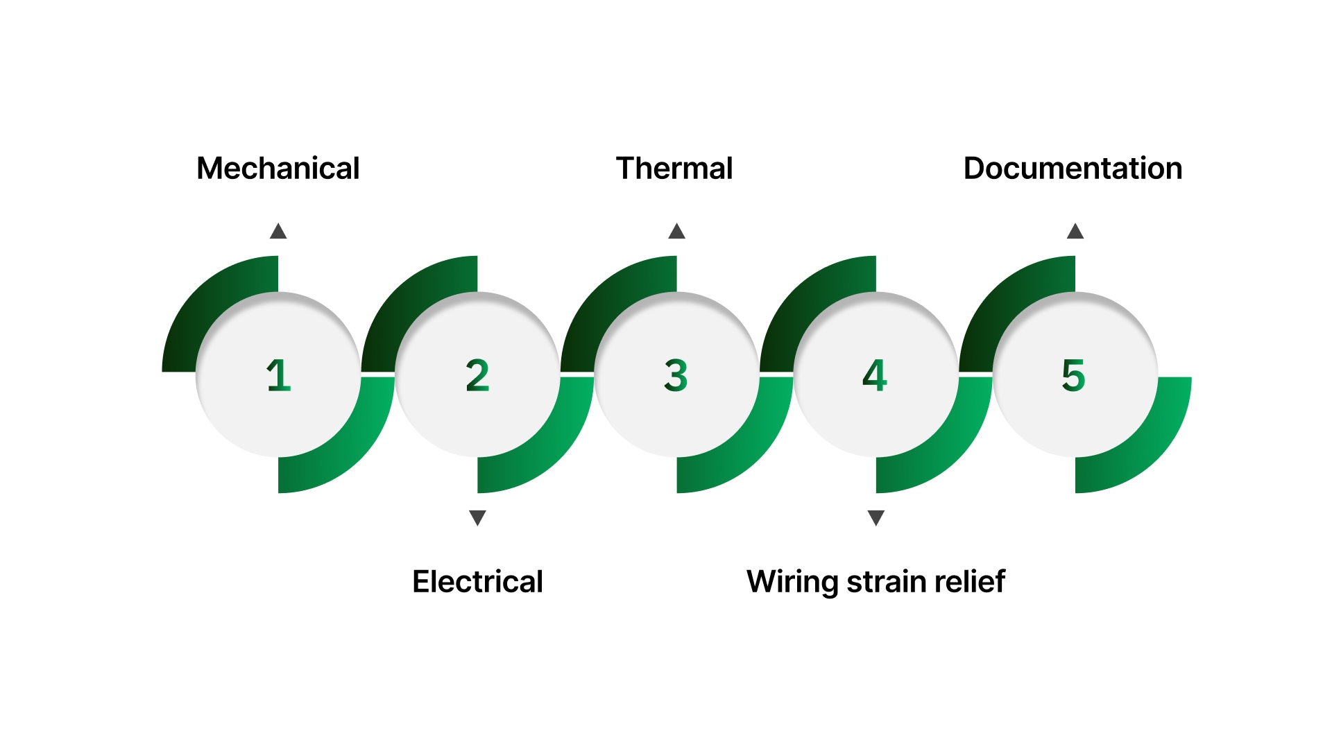
Before you sign off, confirm the rheostat behaves the same way it will in production: door closed, wiring dressed, and the motor running at normal load. This checklist is meant to catch the failure modes that don’t show up on the bench heat soak, vibration loosening, and intermittent wiper contact.
Mechanical (mount + adjustment hardware)
No body rotation: Turn the knob through its range. The rheostat body must not twist in the panel or bracket.
Full travel clearance: Verify the knob/shaft does not rub the panel, label plate, guard, or adjacent hardware at any point.
Knob stays locked: Confirm the set-screw/collet stays tight after cycling and does not slip on the shaft flat/key.
Hardware holds after cycling: After a short run, re-check the bushing nut/jam nut or chassis fasteners for loosening.
Electrical (signal behavior at the wiper/output)
Smooth change: Sweep slowly from min to max. Output should change predictably—no “nothing happens then everything happens” unless that’s expected by design.
No dead spots: There should be no zones where rotation produces little/no change, then suddenly jumps.
No jumps/dropouts: Watch for sudden steps, intermittent opens, or output that briefly rails high/low.
Stable at steady setting: Leave it at the intended setting. It should hold without hunting or drifting due to contact issues.
Thermal (heat rise under real duty)
Temperature rise stabilizes: Run at normal duty long enough to reach thermal steady state. Temperature should level off, not keep climbing.
No odor/discoloration: Any hot phenolic smell, darkening, or brittle insulation is a red flag.
Wiring stays safe: Check nearby conductors and terminals for softening, glossing, or heat exposure from proximity.
Wiring strain relief (the “panel-door” test)
Strain relief holds: Gently tug the motor/rheostat wiring bundle and terminations. The movement must not transfer into lugs/terminals.
Door movement doesn’t stress terminals: Open/close the door (if door-mounted) and confirm nothing pulls, twists, or pinches.
Terminals don’t rotate: Lugs should not twist during knob adjustment or vibration; boots/covers stay seated.
Documentation (so the setting is repeatable)
Record the final setting: Note knob position reference and direction convention (CW increases/decreases).
Capture conditions: Record duty assumptions, approximate enclosure ambient, and whether the check was done with the door closed and the machine loaded.
If this checklist exposes recurring heat, clearance, or stability issues, treat it as a selection-and-install mismatch—then correct the mounting and rating before the next run.
On Line Controls: Closing the Gaps That Cause Repeat Rheostat Failures
If your load test shows overheating, poor repeatability, or “it fits electrically but not mechanically,” you’re at the point where a correct retrofit spec prevents repeat failures.
How On Line Controls Helps You Pass the Under-Load Check
Selecting the correct rheostat switch form factor (panel-mount vs chassis-mount, shaft/bushing style, terminal style/orientation) so the replacement actually fits the enclosure and wiring has proper clearance.
Sizing for real heat and duty cycle so the rheostat isn’t forced to run at the edge once the door is closed and the machine is under load (continuous vs trim use, enclosure temperature, airflow constraints).
Stability and serviceability details that stop repeat downtime (anti-rotation provisions, knob/shaft interface, strain relief approach, terminal hardware that won’t loosen or heat-soak).
Motorized rheostat options when the “switch + knob” should not be manual anymore (remote adjustment, repeatable settings, guarded access, or changeover-driven setpoints).
Why does this help in practice?
On Line Controls supports retrofit selection with mount/shaft/terminal fit + heat/duty matching for industrial panel environments.
If you’re replacing a failed unit or validating a new install, get in touch with On Line Controls and share: rheostat ohms/watts, motor voltage/current, duty cycle, mounting style, enclosure temperature/airflow, and any symptoms you observed under load (drift, hot spot, dead spots, loose setting) and get confirmation on the right configuration before you put it back into service.
Conclusion
A rheostat switch can be a practical retrofit when the requirement is simple reduction, not regulation. It gives you a manual way to limit output, but the trade-off is built in: whatever you “take away” from the motor becomes heat, and performance will always move with load.
The installs that last have one thing in common: they treat the rheostat as a power component, not a knob. That means a series-current wiring approach, a heat-aware rating and mounting choice, and a final check done in the same conditions the panel will actually run in.
When those pieces are handled up front, the rheostat becomes a predictable limiter instead of a recurring failure point.
FAQs
Can you use a rheostat to control an electric motor?
Yes, but only as a series resistance limiter, not true speed regulation. Speed will change with load because the voltage drop changes with motor current. It’s most realistic on brushed DC/PMDC motors and light-duty use.
How do you wire a rheostat switch to a motor?
Wire the rheostat in series with the motor’s power path (2-terminal use: wiper + one end). Put the switch on the supply line, not on the wiper, and use a properly rated fuse/breaker upstream.
Will a rheostat work on an AC induction motor?
Not as proper speed control. Dropping voltage on an induction motor usually causes torque loss, heating, and unstable operation, especially under load. For speed control, a VFD is the standard approach.
What happens if a rheostat is undersized for the motor?
It will run too hot and fail early—common symptoms are burnt insulation, drifting output, dead spots, or intermittent contact. Heat damage often shows up only after the panel is closed and the motor is under real load.
What’s the difference between a rheostat and a motor speed controller?
A rheostat wastes power as heat by dropping voltage in series. A controller (PWM for DC, VFD for AC) regulates electronically, so it’s more efficient and holds speed/torque far better under changing load.