Introduction: The Critical Role of Precision Control in Modern Turbines
A single degree of misalignment in turbine blade pitch can cost power plants thousands in lost efficiency annually. Research shows that just 1 degree of blade pitch error causes 3-5% annual energy production loss in wind turbines, while in steam turbines, a 1% efficiency drop increases unit heat rate by 0.17-0.5%.
These seemingly minor deviations translate to significant revenue losses and operational inefficiencies.
Precision control potentiometers provide continuous position feedback that enables optimization across wind, steam, and hydro turbine applications. These three-terminal variable resistors convert mechanical position into electrical signals, allowing control systems to maintain optimal blade pitch, valve positioning, and guide vane angles with sub-degree accuracy.
The result: turbines operate within their peak efficiency curves, reducing mechanical stress and maximizing energy capture.
TLDR: Key Takeaways
- Real-time position feedback optimizes blade pitch, valve actuation, and yaw control
- Contactless designs last 100+ million cycles vs. 50-100 million for contact types
- Improve turbine efficiency by 2-5% through proper selection and maintenance
- Enable predictive maintenance with continuous signal quality monitoring
What Are Precision Control Potentiometers?
Precision control potentiometers are three-terminal variable resistors engineered to convert mechanical position into electrical signals for industrial control systems. Unlike consumer-grade potentiometers found in audio equipment, industrial units are built for continuous duty cycles in demanding environments.
The "precision control" designation indicates tolerances of ±0.5% or better, with some models achieving ±0.2% independent linearity. These sensors consist of four key components:
- A resistive element that provides the measurement path
- A wiper contact that slides along this element
- A shaft or actuator for mechanical input
- Output terminals that deliver proportional voltage signals
Understanding these components helps explain why industrial-grade units outperform consumer models.
Key Differences from Standard Potentiometers:
| Feature | Industrial Precision | Consumer Grade |
|---|---|---|
| Cycle Life | 50-200+ million movements | <100,000 cycles |
| Linearity | ±0.2% to ±0.5% | ±5% to ±20% |
| Construction | Metal case, ball bearings, stainless steel shaft | Plastic housing, sleeve bearings |
| Temperature Range | -40°C to +125°C | 0°C to 70°C |
| Protection Rating | IP40 to IP67+ | Low IP rating |
When a potentiometer shaft rotates or moves linearly, the wiper contact changes its position along the resistive element. This movement alters the resistance between the wiper and the end terminals, which control systems interpret as precise position data. This simple yet robust principle enables accurate feedback in applications where mechanical position must be monitored continuously.
How Potentiometers Work in Turbine Control Systems
Turbine control systems rely on closed-loop feedback to maintain optimal performance. Precision potentiometers provide the critical position data that enables this continuous optimization.
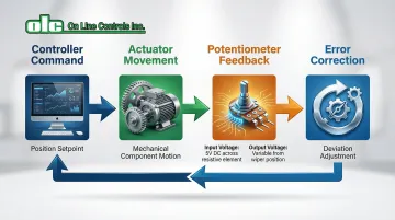
The Command-and-Feedback Loop
The control sequence works as follows: a controller sends a position command to an actuator, which moves the mechanical component (blade, valve, or vane). The potentiometer then reports the actual achieved position back to the controller.
Any deviation between commanded and actual position triggers an immediate correction, ensuring the turbine operates at its intended setpoint.
Voltage Divider Principle
Potentiometers function as voltage dividers. The system applies a fixed voltage across the resistive element's end terminals, and the wiper taps a portion of this voltage.
The output voltage is proportional to the wiper's position along the element—if the wiper is at 50% of travel, the output is 50% of the input voltage. This analog signal provides essentially infinite resolution, limited only by the signal-to-noise ratio of the interface electronics.
Application-Specific Examples
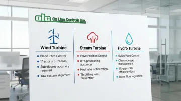
Wind Turbines: Potentiometers monitor blade pitch angle to optimize lift and regulate rotor speed. Given that pitch errors of 1 degree cause power losses of 60-80 kW near rated speeds, sub-degree accuracy is essential. They also control yaw systems, aligning the nacelle perpendicular to wind direction for maximum energy capture.
Steam Turbines: In thermal power plants, potentiometers measure valve piston rod position in electro-hydraulic actuators. Valve positioning accuracy within 0.1% is often required to maintain competitive heat rates and prevent throttling losses.
Hydro Turbines: Potentiometers track guide vane angles to regulate water flow. Precise positioning minimizes clearance gaps that cause efficiency losses—research shows every 1% increase in clearance gap reduces turbine efficiency by approximately 3%.
Types of Potentiometers for Turbine Applications
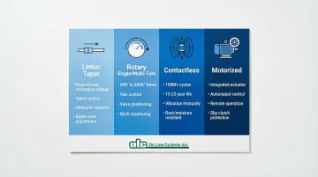
Linear Taper Potentiometers
Linear taper units provide resistance that changes proportionally with position, creating a direct correlation between movement and output voltage. This characteristic makes them ideal for applications requiring straightforward position-to-signal conversion.
Common applications:
- Linear actuators for valve control
- Position sensing in hydraulic systems
- Guide vane adjustment mechanisms where linear motion must be monitored
Rotary Potentiometers
Rotary models come in single-turn and multi-turn variants. Single-turn units typically offer 345° electrical travel, while multi-turn models provide 3,600° (10 turns) or more for applications requiring extended rotation ranges.
Turbine applications:
- Yaw control in wind turbines (single-turn for 360° nacelle rotation)
- Rotary valve positioning in steam systems
- Shaft position monitoring where multiple revolutions must be tracked
Contactless (Non-Contact) Potentiometers
These sensors use magnetic Hall-effect or optical sensing to eliminate physical wear between the wiper and resistive element. This design achieves ratings exceeding 100 million cycles. Some models offer unlimited rotation capability.
Key advantages:
- Extended service life (15-25+ years in typical turbine applications)
- Superior performance in high-vibration environments
- Immunity to dust and moisture contamination that degrades contact-type sensors
- Reduced maintenance requirements and lower total cost of ownership
Motorized Potentiometers
Motorized units integrate a motor-driven actuator with the position sensor in a single assembly. Industrial manufacturers produce these combination units with slip clutch protection and high-quality motor geartrains for reliable operation.
Control applications:
- Automated turbine control systems requiring frequent position adjustments
- Remote valve actuation with position feedback
- Systems where both automatic control and manual adjustment capability are needed
Key Benefits for Turbine Performance Optimization
Real-Time Position Accuracy for Optimal Efficiency
Precise blade pitch or valve positioning keeps turbines operating at peak efficiency curves. Industry data shows that precision feedback systems deliver 2-5% efficiency improvements compared to mechanical-only systems. For a 2 MW wind turbine, a 3% efficiency gain translates to approximately $30,000-$50,000 in additional annual revenue at typical electricity rates.
Reduced Mechanical Wear Through Controlled Movements
Smooth, monitored position changes reduce shock loads and vibration compared to open-loop systems. Gradual adjustments minimize stress on gear trains, bearings, and actuators, extending component life and reducing maintenance intervals.
The cost implications are significant: scheduled maintenance costs 60-80% less than emergency repairs during unplanned turbine downtime.
Enhanced Safety Through Position Verification
Potentiometers provide critical safety functions by confirming that components are in their intended positions. Critical examples include:
- Verifying steam valves are fully closed before maintenance
- Confirming blade pitch in emergency shutdown scenarios
- Ensuring guide vanes remain within safe operating ranges
Safety-critical applications commonly use redundant potentiometer systems. Multi-section units with 2 or 3 electrically independent sensors on a single shaft enable 2oo3 voting schemes that tolerate component failures without compromising safety.
Predictive Maintenance Capabilities
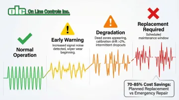
Monitoring potentiometer signal quality reveals approaching failures before complete breakdown. Key warning signs include:
- Increased signal noise from wiper wear
- Dead zones during rotation (resistive element damage)
- Calibration drift exceeding ±2% from baseline
- Intermittent dropouts indicating connection issues
Detecting these indicators allows scheduled replacement during planned maintenance windows rather than emergency repairs. The cost savings are substantial—planned component replacement typically costs 70-85% less than emergency repairs that require turbine shutdown and expedited parts procurement.
Adaptability to Variable Operating Conditions
Potentiometer feedback enables turbines to automatically adjust to changing conditions: wind speed variations, load fluctuations, and steam pressure changes. This real-time adaptation maximizes capacity factor (the ratio of actual output to theoretical maximum) and energy capture across varying operating conditions.
Common Challenges and Solutions in Turbine Environments
Environmental Challenges
Turbine environments subject sensors to harsh conditions: temperature extremes (-40°C to +125°C), high humidity, constant vibration, and electromagnetic interference from generators and drives.
Solutions:
- Select sensors with appropriate IP67 or IP69K sealing for exposed locations
- Specify units with conformal coatings on electronics to resist moisture
- Implement proper grounding and shielded cabling to minimize EMI
- Choose industrial-rated components tested to IEC 60068 standards for 20g vibration and 50g shock
Wear and Contamination Issues
Beyond environmental stresses, physical wear poses another challenge. Dust infiltration, moisture ingress, and wiper wear create signal noise or dead zones that compromise position accuracy.
In contact-type potentiometers, the physical interface between wiper and resistive element eventually degrades.
Solutions:
- Specify contactless designs for high-cycle applications (100+ million movements expected)
- Install protective bellows on linear potentiometers in dusty environments
- Implement regular inspection schedules (semi-annual for critical applications)
- Consider sealed units with IP65+ ratings for harsh conditions
Signal Degradation and Calibration Drift
Even with proper environmental protection, internal aging affects performance. Resistance element aging causes position errors over time. Temperature cycling, vibration, and electrical stress gradually shift the output characteristics away from factory calibration.
For applications requiring motorized position control, manufacturers like On Line Controls offer potentiometers designed for extended lifespan in industrial environments, reducing the frequency of recalibration and replacement.
Recommended practices:
- Document baseline signal characteristics at commissioning
- Perform periodic calibration verification (annually for critical systems)
- Establish replacement criteria based on drift thresholds (typically >2% deviation)
- Monitor signal quality continuously using control system diagnostics where available
Maintenance Best Practices for Turbine Potentiometers
Regular maintenance ensures potentiometers deliver accurate position feedback for optimal turbine control. Establishing inspection schedules and diagnostic protocols prevents unexpected failures and extends equipment lifespan.
Inspection Frequency:
- Visual checks during routine turbine maintenance (quarterly or semi-annually)
- Signal quality testing semi-annually for critical control loops
- Comprehensive diagnostic testing annually
Diagnostic Procedures:
- Measure resistance across terminals at multiple positions and compare to specifications
- Verify output voltage at known positions (0%, 25%, 50%, 75%, 100% of travel)
- Assess signal noise by monitoring output voltage stability over time
- Check for dead zones by slowly rotating through full travel range while monitoring output
Replacement Criteria:
Replace potentiometers when:
- Signal drift exceeds ±2% deviation from baseline calibration
- Dead zones appear during rotation (indicating resistive element damage)
- Signal noise increases significantly (suggesting wiper wear)
- Physical damage to shaft, housing, or terminals is evident
- Preventive schedules indicate replacement (5-10 years for contact types, 15-20+ years for contactless)
These maintenance principles apply broadly to precision control potentiometers across industrial applications. For motorized potentiometer systems specifically, manufacturers like On Line Controls recommend never adjusting factory-set slip clutches, as this can void warranties and render units inoperable.
These protective mechanisms are calibrated to prevent gear train damage while allowing manual adjustment when motors are off.
Frequently Asked Questions
What is the typical lifespan of a potentiometer in turbine applications?
Contact-type potentiometers typically last 5-10 years with 50-100 million movement cycles, depending on duty cycle and environmental conditions. Contactless designs extend this to 15-25+ years with ratings of 100-200 million cycles or more.
How do I know when a potentiometer needs replacement?
Key warning signs include erratic position readings, dead zones where output doesn't change despite shaft movement, increased signal noise on displays, physical damage to components, and calibration drift exceeding ±2%.
Can potentiometers withstand the vibration in wind turbine nacelles?
Yes, industrial potentiometers rated to IEC 60068-2-6 withstand 20g vibration at frequencies from 5-2000 Hz. Contactless designs offer superior performance by eliminating mechanical wear accelerated by vibration.
What's the difference between potentiometers and encoders for turbine control?
Potentiometers provide analog absolute position with infinite resolution, simpler interfacing, and lower cost. Encoders deliver digital signals with discrete resolution (10-12 bit) and superior noise immunity. Choice depends on your control system architecture.
Are digital potentiometers better than analog for turbine applications?
Digital potentiometers offer remote programming and advanced diagnostics but require more complex interfacing. Analog units provide simpler integration and proven reliability. For new digital control systems, digital units enable better remote monitoring and predictive maintenance.
How does potentiometer accuracy affect overall turbine efficiency?
Position accuracy of ±0.5% enables turbines to stay within optimal performance curves, improving annual energy production by 2-5%. For a typical 2 MW wind turbine, this translates to $30,000-$50,000 in additional annual revenue.