Introduction
A single tension spike during medical tubing extrusion can ruin an entire production run. Potentiometers provide the precise tension feedback that engineers and operators need in plastic tubing extrusion, web handling, and converting operations. In medical tubing production and high-precision manufacturing, these sensors deliver the analog position signals that closed-loop control systems require to maintain consistent product quality.
The practical challenges are significant. Potentiometers require proper installation, environmental protection, and integration with control systems. Improper setup often leads to signal drift, inconsistent tension readings, or premature component failure.
As manufacturing tolerances tighten, potentiometer-based tension control has become essential in operations where even minor tension variations cause defects—wrinkled film, stretched tubing, or uneven winding that renders products unusable.
This guide addresses these challenges by explaining how to use potentiometers correctly in real-world tension control applications, covering setup, operation, and maintenance practices that ensure long-term performance.
Key Takeaways
- Potentiometers convert dancer arm position into electrical signals for closed-loop tension control
- Provide ratiometric feedback, cost-effective sensing, and analog system integration
- Installation requires ±0.5° alignment, shielded cabling, and IP65+ sealing
- Monitor for signal noise, mechanical wear, and environmental contamination during operation
- Select industrial-grade components designed for 5-100 million cycles and 10+ year service life
When Should You Use Potentiometers for Tension Control?
Position-Based Feedback Applications
Potentiometers excel when you need position-based tension feedback in closed-loop control systems, particularly for dancer arm positioning, brake/clutch control, and web accumulator systems.
They convert the mechanical position of a tension element into a proportional voltage signal that your control system uses to adjust drive speed or brake torque, maintaining consistent web tension throughout processing.
Where Potentiometers Outperform Alternatives
Cost-effective scenarios include:
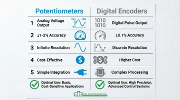
- Applications requiring analog voltage output (0-10V or ratiometric) that integrates directly with legacy PLCs
- Moderate-speed operations where ±1-2% accuracy works well versus the higher precision of digital encoders
- Infinite resolution analog signals that simplify control loop tuning compared to discrete digital pulses
- Diameter sensing and dancer position feedback, where direct voltage proportional to position eliminates signal processing complexity
Potentiometers offer a superior accuracy-to-cost ratio for dancer arm position feedback and diameter sensing applications where the precision of encoders isn't strictly required.
When Potentiometers Are Misused
Avoid potentiometers in these scenarios:
- High-vibration environments without proper damping—mechanical shock accelerates wiper wear
- Extremely high-speed applications requiring sub-millisecond response times
- Corrosive environments without adequate sealing (minimum IP65 rating)
- Applications where digital precision is mandatory for regulatory compliance
Operational Context
Potentiometers work best in controlled industrial environments with:
- Regular maintenance access
- Tension control accuracy requirements of ±1-2%
- Control systems that process analog voltage signals
- Mechanical cycle life considerations (typically 5 million to 100 million cycles depending on quality)
- Appropriate environmental protection for your application (IP rating)
What You Need Before Using Potentiometers for Tension Control
Mechanical Mounting System
Precision brackets or arms that prevent side-loading and ensure rotational or linear alignment within manufacturer specifications (typically ±0.5° for rotary types). Misalignment causes accelerated wear and signal errors.
Use flexible couplings (bellows or Oldham types) to handle slight angular and radial misalignment between the machine shaft and sensor, as rigid coupling causes premature failure.
Critical load limits:
- Observe shaft load specifications strictly—typically 15-45 N maximum (axial/radial)
- Exceeding these limits destroys bearings and sensor elements
- Axial misalignment (eccentricity) directly causes linearity errors and reduced rotational life
Compatible Control System
Your tension controller or PLC must be capable of:
- Reading analog voltage signals (typically 0-10VDC or ratiometric)
- A/D conversion resolution of at least 12-bit (industrial systems typically use 16-bit for finer position detection)
- Sampling rates of 300-700 µs per channel for responsive tension control
- Input impedance >100 kΩ to prevent loading the potentiometer wiper
- Configurable input filtering (typically 3 kHz) to suppress mechanical noise while maintaining loop response
Environmental Protection
Minimum requirements:
- IP65 or higher rated enclosures for dusty or wet environments
- Proper cable glands and consideration of temperature range (-40°C to +100°C typical)
- Sealed potentiometers in washdown or contaminated converting environments
- Protection from direct water/chemical exposure
Industrial-grade potentiometers meeting IEC 60529 standards survive harsh conditions that destroy commercial-grade units within months.
Electrical Infrastructure
Essential elements:
- Clean power supply (typically 10-24VDC regulated) with stable voltage
- Shielded cabling to prevent EMI interference—analog I/O lines are highly susceptible to electrical noise
- Proper grounding to avoid ground loops (single-point grounding at cabinet end only)
- Surge protection if operating near high-power equipment or welding operations
Follow ISA90 and IEEE Std 142 grounding standards to prevent noise in low-level analog signals.
Skill and Supervision Requirements
Beyond the physical hardware, you'll need technicians trained in mechanical alignment, electrical troubleshooting, and control system integration. Initial setup often requires oscilloscope verification of signal quality and systematic commissioning procedures.
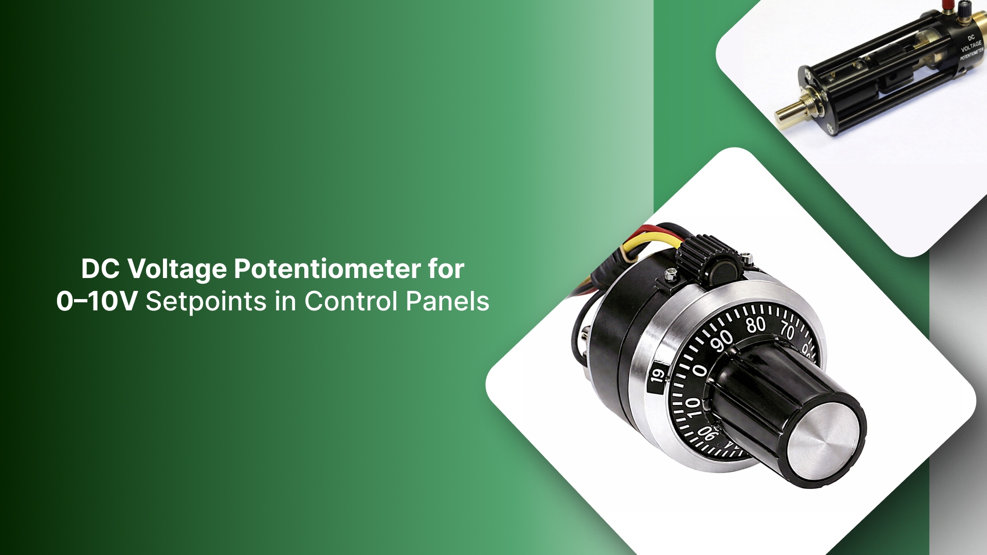
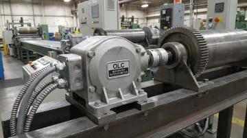
For tension control in plastic tubing extrusion, motorized potentiometers like those from OLC come factory-set with no field calibration required, offering 10-20 year service life with 50 million turn rotational life in premium conductive plastic models.
How to Use Potentiometers for Tension Control (Step-by-Step)
Correct potentiometer usage follows a defined installation and commissioning sequence.
Skipping steps like mechanical alignment verification or electrical signal testing leads to erratic tension control, premature wear, or system instability that's difficult to diagnose later.
Setup and Preparation
Mechanical installation:
- Mount potentiometer shaft concentric with the rotating or linear element it's measuring
- Use flexible couplings to eliminate side loads—rigid coupling causes premature bearing failure
- Confirm smooth rotation/travel through full range without binding
- Check that mechanical stops don't exceed potentiometer's electrical travel limits
Once mechanical installation is complete, proceed with electrical connections:
Electrical connections:
- Wire potentiometer according to manufacturer specifications (typically power, ground, and signal wiper)
- Use shielded cable with shield grounded at one end only (cabinet end)
- Check supply voltage stability with multimeter before energizing
- Confirm for proper polarity—reversed polarity damages some models
Common setup errors to avoid:
- Over-tightening mounting hardware causing housing distortion
- Improper coupling alignment creating side loads that accelerate wear
- Inadequate cable strain relief leading to wire fatigue
- Failure to protect connections from environmental contamination
Initiating Use
System power-up sequence:
- Energize potentiometer power supply first
- Verify output signal is present and stable using multimeter or oscilloscope
- Confirm signal changes smoothly through mechanical travel range
- Integrate with control system and verify signal recognition
Set dancer arm or tension element to neutral position, verify potentiometer output corresponds to expected mid-range voltage (typically 5V for 0-10V output), and establish this as system zero reference.
Indicators of correct initiation:
- Stable voltage reading without noise or drift (signal noise should be <100-150 mV)
- Linear voltage change corresponding to mechanical position change
- Control system recognizing signal within expected range
Operating Potentiometers Correctly
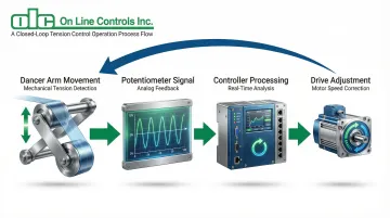
The potentiometer continuously converts mechanical position into voltage signal that your control system reads to adjust brake/clutch torque or drive speed, maintaining dancer arm or tension element at setpoint position.
This closed-loop feedback maintains web tension within ±1-2% accuracy in properly configured systems.
To maintain this precision, respect these operating limits:
Operating limits:
- Avoid mechanical over-travel that damages internal stops
- Stay within rated electrical specifications (voltage/current)
- Respect environmental limits (temperature, contamination) that affect long-term reliability
- Keep wiper current ≤1 µA to prevent element damage
Stable potentiometer signal equals consistent tension feedback, which allows control system to maintain product quality. Signal instability from worn potentiometers causes tension variations that create defects in wound rolls or processed web.
Monitoring During Use
Watch for these indicators:
- Sudden signal jumps indicating mechanical wear or electrical issues
- Gradual signal drift suggesting contamination or component aging
- Excessive noise in signal trace visible on controller display
- Erratic tension control behavior or increased frequency of tension-related defects
Physical inspection signs:
- Physical resistance when manually moving dancer arm
- Visible wear or corrosion on potentiometer housing or shaft
- Loose mechanical couplings or mounting hardware
Periodic signal quality checks:
- Use oscilloscope to verify clean analog signal without noise spikes
- Measure signal-to-noise ratio against baseline
- Compare current performance to baseline established during commissioning
Maintenance and Long-Term Care
Scheduled maintenance tasks:
- Inspect mechanical coupling for wear every 3-6 months
- Verify electrical connections remain tight and corrosion-free
- Clean external surfaces if contamination is present
- Document signal quality measurements for trend analysis
Potentiometers in industrial tension control applications typically last 10-20+ years with proper care. Neglect of basic inspection and protection leads to premature failure, unexpected downtime, and quality issues.
Replacement timing:
- Plan replacement when signal quality degrades beyond acceptable limits
- Replace when mechanical resistance increases noticeably
- Consider proactive replacement when approaching manufacturer's rated cycle life
- Schedule replacement during planned maintenance to prevent production disruptions
Where Potentiometers Are Commonly Used in Tension Control
Manufacturing Workflow Applications
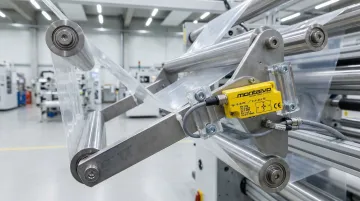
Dancer arm position sensing represents the most common application. A rotary potentiometer mechanically links to the dancer arm pivot point. As the dancer moves to absorb tension fluctuations, the potentiometer provides position feedback (0-10V) to the controller.
This feedback allows the controller to adjust driven roll speed automatically, keeping the dancer centered and tension consistent.
Another common application is brake/clutch feedback control in unwinding/rewinding operations. A follower arm rides on the unwind/rewind roll, and the potentiometer measures the arm's angle to determine roll diameter.
As diameter decreases, the control system reduces brake torque proportionally to maintain constant tension.
Accumulator positioning uses linear or multi-turn rotary potentiometers to track accumulator carriage position in plastic tubing extrusion lines. This feedback coordinates speed transitions as the accumulator fills or empties, allowing continuous operation during roll changes.
Industry-Specific Usage Patterns
Plastic extrusion operations—including medical tubing manufacturers—rely on potentiometers for continuous tension control. Consistent wall thickness depends on maintaining precise material tension throughout the extrusion process.
Printing and converting industries employ potentiometers in multi-zone web tension systems where multiple dancer arms control tension across different process sections—printing stations, drying ovens, and rewinding.
Packaging operations use them for temporary web storage during splicing, where accumulators must maintain constant downstream tension while operators join new material rolls.
Best Practices for Using Potentiometers Effectively
Select Industrial-Grade Components
Choose products designed for 10+ year service life, sealed to IP65 or better, and backed by comprehensive technical support. Key specifications to verify:
- Cycle life: 5-100 million cycles (industrial) vs. 10,000-100,000 cycles (commercial)
- Standards compliance: IEC 60393 for standardized performance
- Environmental rating: IP65 minimum for harsh environments
For example, OLC's conductive plastic motorized potentiometers deliver 50 million turn life expectancy with 10-25 year operational lifespan and require no calibration throughout their service life.
Implement Proper Environmental Protection
Environmental factors directly impact potentiometer longevity. Essential protection measures include:
- Use sealed enclosures in contaminated environments
- Maintain recommended operating temperature ranges (-40°C to +100°C)
- Protect from direct water/chemical exposure
- Ensure adequate ventilation to prevent condensation buildup
IP65 rating is critical for survival in washdown or dusty converting environments where unprotected sensors fail within months.
Follow Electrical Best Practices
Proper wiring and grounding prevent signal interference and ensure accurate readings:
- Always use shielded cable for signal wiring—analog signals are Category 2 conductors highly susceptible to EMI
- Maintain proper grounding discipline: shield grounded at one end only to avoid ground loops
- Separate signal cables from power cables by minimum 6 inches (more without conduit)
- Cross power lines at right angles when separation isn't possible
- Install surge protection on power supplies in electrically noisy environments
Establish Disciplined Inspection Routines
Preventive maintenance extends potentiometer life and prevents unexpected failures:
- Create schedule based on operating hours or production cycles (typically 3-6 month intervals)
- Document baseline performance metrics during commissioning
- Trend signal quality measurements over time to detect gradual degradation
- Train operators to recognize early warning signs: erratic control, increased defects, mechanical resistance
Design Systems with Maintenance Accessibility
Position potentiometers where technicians can easily inspect and service them. Provide adequate clearance for coupling removal. Consider redundant sensing in critical applications where downtime costs exceed sensor investment. Design with future replacement in mind—even quality potentiometers eventually wear out after millions of cycles.
Conclusion
Using potentiometers correctly in tension control is less about technical complexity and more about disciplined installation, proper environmental protection, and systematic monitoring throughout their service life.
The difference between a potentiometer that fails after two years and one that delivers 20 years of reliable service comes down to three practices:
- Following proper mechanical alignment procedures during installation
- Implementing adequate environmental sealing against contaminants
- Maintaining disciplined inspection routines throughout service life
These practices protect both immediate performance—consistent tension control and product quality—and long-term cost efficiency. With proper care, quality motorized potentiometers routinely deliver 10-20+ years of reliable service in demanding industrial environments.
Frequently Asked Questions
What is the function of tension control potentiometers?
Tension control potentiometers convert mechanical position of dancer arms, brake actuators, or tension elements into electrical voltage signals (typically 0-10VDC). Control systems use these signals to maintain consistent web or material tension throughout processing operations.
What are the four types of potentiometers?
The four main types are rotary (angular position), linear (straight-line motion), membrane (sealed panel controls), and digital (electronically controlled). Tension control typically uses rotary or linear types with conductive plastic elements for high-cycle applications.
Does a potentiometer control resistance?
Potentiometers are variable resistors, but in tension control they function as voltage dividers providing position feedback signals. The wiper position determines output voltage proportional to mechanical position, which the control system interprets as tension element position.
What is a CCW potentiometer?
CCW (counterclockwise) refers to the rotation direction that increases the potentiometer's output signal. This directional setup is important during installation to ensure the control system receives increasing voltage as tension increases, preventing inverted control response that would destabilize the tension loop.
How often should tension control potentiometers be inspected?
Visual inspection every 3-6 months is recommended in typical industrial environments, with more frequent checks (monthly) in contaminated or high-cycle applications. Perform periodic signal quality verification using oscilloscope or multimeter to detect gradual degradation before it affects product quality.
What causes potentiometer signal drift in tension control systems?
Common causes include contamination on the resistive element (dust, moisture, process materials), temperature variations, worn mechanical components, electrical interference from nearby equipment, or improper grounding creating signal noise.