Introduction: Why Motor Potentiometer Lifespan Matters
When a motor potentiometer fails on an extrusion line or heavy equipment control system, the cost extends far beyond the component itself. Industrial downtime can run between $10,000 and $500,000 per hour, making premature motor pot failure a costly problem to ignore.
Yet many engineers still specify potentiometers based on initial price rather than expected service life. That decision often leads to repeated replacements, unplanned downtime, and mounting maintenance costs that dwarf the original savings.
The lifespan of industrial motor potentiometers varies dramatically, from as few as 50,000 cycles in basic carbon units to over 20 million cycles in premium conductive plastic designs. Understanding what drives these differences — resistive material, wiper design, environmental protection, and manufacturing quality — enables you to select components that match your actual duty cycle and deliver genuine long-term value. This article breaks down what determines motor pot lifespan, how to evaluate specifications, and what to look for when replacing or upgrading.
TLDR: Motor Potentiometer Lifespan Quick Facts
- Premium conductive plastic motor pots: 10–50 million cycles — typically 10–25+ years in service
- Cermet industrial-grade units: up to 2 million cycles, or 5–10 years in demanding environments
- Wirewound motor pots range widely: 100,000 to 10 million cycles depending on winding density and wiper design
- Basic carbon film types wear out fastest — 50,000–500,000 cycles, or just 1–3 years under continuous industrial use
- Lifespan depends most on resistive element material, wiper contact design, IP-rated sealing, and how hard the unit runs day-to-day
What Determines Industrial Motor Potentiometer Lifespan
Core Lifespan Metric: Mechanical Life Cycles
Potentiometer lifespan is measured in mechanical rotations (cycles), not calendar years. A "cycle" constitutes one complete rotation for rotary potentiometers or full travel range for linear types. This metric provides the only meaningful comparison across manufacturers because the same potentiometer might last 2 years in a high-speed servo application or 20 years in an intermittent adjustment role.
IEC 60393 endurance testing establishes the industry standard for measuring potentiometer life. This specification distinguishes between:
- Mechanical endurance: Rotational life without electrical load
- Electrical endurance: Life under rated power conditions
Leading manufacturers report cycle ratings based on IEC 60393-1 and IEC 60393-3 test protocols, which keeps datasheets comparable across brands. When evaluating specifications, verify that claimed cycle life references these standards. Manufacturers adhering to IEC testing typically produce more durable products with predictable performance degradation curves.
The Role of Resistive Element Material
The resistive track material is the primary determinant of mechanical life. Physical wear occurs as the wiper contact moves across the resistive surface, gradually abrading the material. Different technologies differ sharply in wear resistance:
Material performance comparison:
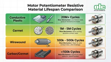
| Material | Typical Cycle Life | Primary Wear Mechanism |
|---|---|---|
| Conductive Plastic (Premium) | 10–50 million cycles | Surface abrasion of polymer; gradual contact resistance increase |
| Cermet (Ceramic-Metal) | 2 million cycles | Extremely hard surface; wiper wears before element |
| Wirewound (Precision) | 100,000–10 million cycles | Physical abrasion of wire turns; stepped output |
| Carbon/Cermet (Standard) | 50,000–500,000 cycles | Rapid surface degradation; noise increase |
Each material ages differently in service:
- Conductive plastic offers self-lubricating properties and distributes wear evenly across the track, explaining its superior cycle count
- Cermet surfaces are so hard that the wiper typically wears out before the track degrades
- Wirewound designs wear at the point of wiper-to-wire contact, producing increasing noise and eventual wire breakage
Wiper Contact Design and Quality
The wiper creates the electrical connection while traveling across the track, making its material, geometry, and contact pressure critical to longevity. Even the most durable resistive element degrades ahead of schedule when paired with a poorly designed wiper.
Multi-finger wiper designs distribute wear across multiple contact points. If one finger loses contact due to debris or vibration, others maintain circuit continuity. This approach reduces Contact Resistance Variation (CRV) from 5% in single-finger designs to 1–2% in multi-finger configurations, which is essential for smooth motor control feedback.
Precious metal alloys (such as Paliney) prevent oxidation and maintain low contact resistance over millions of cycles. Combined with specialized lubricants applied to the resistive surface, these materials minimize friction while preventing corrosion that would otherwise increase noise and accelerate wear.
Manufacturing Quality and Precision
Manufacturing tolerances directly impact both initial performance and service life. Uniform resistive layer application ensures consistent electrical characteristics and predictable wear patterns. Poor application leads to thin spots that fail prematurely and thick areas that cause linearity errors.
Precision in mechanical components also matters. Tight tolerances on bearings, shaft alignment, and housing fit prevent side-loading and uneven contact pressure. When those tolerances slip, localized wear patterns develop — producing dead spots and erratic output well before the rated cycle life.
Environmental Protection and Sealing
Contamination is one of the quickest paths to early failure. Dust particles act like grinding compound between the wiper and track, while moisture creates corrosion and electrical leakage paths. The IP (Ingress Protection) rating quantifies a potentiometer's resistance to these threats.
IP rating impact on lifespan:
- IP65/IP67 sealed units: Dust-tight and water-resistant; suitable for industrial environments. Units like the Novotechnik IPE6000 achieve 100 million movements largely because contaminants never reach the resistive element
- IP40/IP50 standard units: Protected against solid objects >1mm; appropriate only for clean panel environments. Exposure to industrial conditions causes rapid failure from track contamination
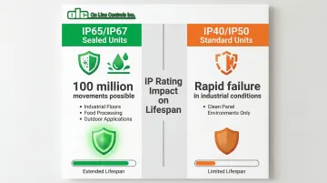
Operating a standard IP40 unit in a dusty manufacturing environment can reduce its effective lifespan by 80% or more compared to the same unit in a clean control room.
Expected Lifespan by Potentiometer Type and Material
Conductive Plastic Motor Potentiometers
Cycle life: 10-50 million cycles (10-25+ years in typical applications)
Conductive plastic technology delivers the longest service life of any contact-based potentiometer. The plastic-based resistive element provides even wear characteristics and self-lubricating properties that minimize friction. Premium industrial units achieve 10-20 million cycles as standard, with specialized designs reaching 50 million cycles.
This longevity justifies higher initial costs in applications where:
- Continuous or high-frequency operation accumulates cycles rapidly
- Replacement access is difficult (offshore equipment, aircraft systems)
- Downtime costs far exceed component costs
- Precision feedback must remain stable over years
Quality varies significantly between manufacturers claiming "conductive plastic" construction. Verify that specifications reference IEC 60393 testing and request data on contact resistance variation over the rated cycle life. The best units maintain linearity within ±1% and CRV below 2% even after millions of cycles.
Wirewound Motor Potentiometers
Cycle life: 100,000-10 million cycles depending on design (5-10 years in precision applications)
Wirewound potentiometers use a precisely wound resistance wire as the element. The wiper makes contact with individual wire turns, creating a stepped output rather than the infinitely smooth response of conductive plastic. This stepped nature limits wirewound use in applications requiring continuous smooth motion feedback.
Precision wirewound designs incorporate fine wire windings and optimized alloy selection to extend life toward 10 million cycles. They perform well where:
- High precision and stability are required
- The stepped output is acceptable (or filtered electronically)
- Operating temperatures exceed conductive plastic limits
- Power dissipation requirements favor wirewound construction
Standard wirewound units typically rate at 100,000-1 million cycles—adequate for infrequent manual adjustment applications but insufficient for continuous servo feedback.
Cermet and Carbon Film Motor Potentiometers
Cycle life: 50,000-2 million cycles (1-10 years depending on quality and application)
Cermet (ceramic-metal composite) technology spans a wide quality range. Industrial-grade cermet units like the Vishay P30L achieve 2 million mechanical cycles through extremely hard surface coatings. In these designs, the wiper typically wears out before the track degrades, and failure modes are predictable.
Standard carbon and cermet units rate at only 50,000-500,000 cycles. Lower-cycle units are suited for:
- Cost-sensitive applications with infrequent adjustment
- Prototype and development equipment
- Applications where replacement is simple and downtime is acceptable
The performance degradation curve is steeper than conductive plastic—expect noticeable increases in noise and contact resistance variation after 50-70% of rated life. Using cermet or carbon film potentiometers in demanding continuous-duty applications represents a poor long-term investment: frequent replacements quickly exceed the upfront cost of a premium unit.
Hybrid and Specialty Motor Potentiometer Designs
Hybrid elements combine conductive plastic material applied over a wirewound base, delivering lower inductance, better resolution, and longer life (typically 10 million cycles) than standard wirewound while maintaining some of wirewound's stability advantages.
Contactless alternatives eliminate the primary failure mechanism entirely:
- Hall-effect sensors: Use magnetic field sensing with no physical contact between moving parts. Life expectancy exceeds 25 million shaft revolutions, limited only by bearing wear
- Magnetic encoders: Achieve 100 million movements with IP65 sealing, ideal for heavy equipment where replacement access is difficult
Trade-offs include higher initial cost, increased circuit complexity, and digital resolution (typically 12-bit/4096 steps) rather than true analog output. For extreme-duty-cycle applications—continuous rotation, high vibration, harsh environments—contactless technology delivers the lowest total cost of ownership despite premium pricing.
Lifespan in Real-World Time: Converting Cycles to Years
Knowing your duty cycle turns rated cycles into a concrete replacement schedule. Use this formula:
Years = Rated Cycles ÷ (Rotations per Hour × Operating Hours per Day × Days per Year)
Example 1: Continuous extrusion line servo feedback
- Potentiometer: 10 million cycle conductive plastic unit
- Duty cycle: 10 rotations/hour × 20 hours/day × 300 days/year = 60,000 cycles/year
- Expected life: 167 years (bearing and motor failure will occur first)
Example 2: Intermittent speed adjustment
- Potentiometer: 500,000 cycle cermet unit
- Duty cycle: 2 rotations/hour × 8 hours/day × 250 days/year = 4,000 cycles/year
- Expected life: 125 years (again, other components fail first)
Example 3: High-speed servo with dithering
- Potentiometer: 2 million cycle cermet unit
- Duty cycle: 100 rotations/hour × 16 hours/day × 300 days/year = 480,000 cycles/year
- Expected life: 4.2 years (realistic replacement interval)

Run the numbers for your specific duty cycle before selecting a type—the right choice in a low-cycle application may be dangerously undersized in a high-speed servo context.
Real-World Factors That Shorten Motor Pot Life
Operating Environment Challenges
Temperature extremes accelerate wear through several mechanisms. Thermal expansion and contraction stress the wiper-track interface, high temperatures degrade lubricants, and low temperatures make materials brittle and increase contact resistance. Industrial potentiometers typically rate for -40°C to +120°C. Exceeding those limits dramatically shortens service life.
Contamination is the most common cause of premature failure. Abrasive particles — metal dust, dirt, process residue — enter unsealed housings and act like grinding compound between wiper and track. A single contamination event can cut remaining life by 50% or more. Moisture corrodes the resistive element and wiper contact, increasing noise and eventually causing open circuits.
Vibration and shock affect mechanical components and contact integrity. High-grade industrial sensors withstand 20g vibration without contact separation. Standard units may experience intermittent signal loss that causes motor drive faults and system instability.
Electrical Stress and Overload
Operating beyond rated voltage, current, or power specifications creates thermal stress that permanently degrades the resistive element. Each potentiometer carries a maximum power dissipation rating (typically 0.5–5 watts) defined at a specific ambient temperature. Manufacturers publish derating curves: a unit rated 0.5W at 70°C, for example, must be derated to 0W at 125°C.
Key electrical stress factors to control:
- Wiper current overload — exceeding limits burns spots onto the track; even a low-ohm multimeter reading can damage conductive plastic elements
- Current limits by type — conductive plastic units cap wiper current at 5 mA; wirewound types allow up to 50 mA
- Voltage spikes and noise — transients stress the resistive element and can cause immediate failure; proper filtering and circuit protection are essential
Application-Specific Stress Factors
High-speed operation increases wiper friction and generates heat at the contact interface. Manufacturers specify maximum rotational speeds — often around 5 RPM for precision units — and exceeding those limits accelerates wear exponentially.
Dithering or hunting describes constant micro-adjustments around a setpoint, common in servo feedback loops and control valve applications. This concentrates wear on a narrow section of track, producing a dead spot or noise spike at that position while the rest of the track stays undamaged. The unit fails functionally with 90% of its track unused.
Positional bias occurs when the potentiometer spends most operating time in one position. Similar to dithering, this creates a localized worn area. Applications with known positional bias benefit from periodic recalibration to distribute wear across the full track.
How to Maximize Your Motor Potentiometer's Lifespan
Proper Installation and Mounting
Shaft alignment is the first thing to get right. Side-loading from misaligned couplings creates uneven wiper pressure and accelerates bearing wear. Use flexible couplings that accommodate slight misalignment, and verify alignment during installation with dial indicators.
Mounting hardware torque must follow manufacturer specifications — over-tightening distorts the housing and creates internal mechanical stress, while under-tightening allows vibration that damages connections and bearings.
Environmental protection starts at installation. Keep sealed units sealed: no drilling additional holes, no removing gaskets. Protect electrical terminals with appropriate enclosures and route cables away from high-voltage lines to minimize electrical noise.
Operating Within Specifications
Stay within electrical ratings at all times:
- Operate at ≤50% of rated power dissipation to minimize thermal stress
- Never exceed maximum wiper current (5mA for conductive plastic, 50mA for wirewound)
- Provide adequate derating for high ambient temperatures
- Include circuit protection against voltage spikes and transients
Mechanical limits matter just as much. Respect maximum rotational speed and avoid overtravel past mechanical stops. The slip clutch in quality motorized potentiometers protects against overtravel damage — but if the clutch engages repeatedly, that's a system problem that needs correction, not a feature to rely on.
Regular Inspection and Preventive Maintenance
For high-cycle critical applications, check performance every 100,000 cycles or quarterly — whichever comes first. Monitor:
- Output signal noise (Contact Resistance Variation)
- Linearity deviation from initial calibration
- Mechanical feel (smoothness, torque, play in bearings)
- Physical condition (housing cracks, loose connections, contamination)
Testing means measuring contact resistance while rotating the shaft (watching for spikes or dead spots) and verifying linearity against the datasheet. A CRV increase beyond 3% or linearity deviation beyond ±5% indicates the unit is nearing end-of-life.
On cleaning: follow manufacturer guidance and don't assume it helps. Many sealed units should never be opened. Wirewound types with accessible elements may benefit from careful cleaning with appropriate solvents, but the wrong solvent damages conductive plastic elements permanently.
Selecting the Right Potentiometer for Your Duty Cycle
Match the potentiometer's life rating to your application requirements. For a 5-year replacement interval in an application accumulating 400,000 cycles/year, specify a unit rated for at least 2.5 million cycles (a 25% safety margin built in).
The numbers make the case clearly:
| Option A: $50 Standard Unit (500K cycles) | Option B: $200 Premium Unit (10M cycles) | |
|---|---|---|
| Replacement interval | Every 15 months | 25+ years |
| Parts cost (5 years) | $200 | $200 |
| Downtime events (5 years) | 3 × ($10,000 + $500 labor) | 0 |
| 5-year total | $31,700 | $200 |

The premium unit pays for itself by preventing a single downtime event.
For truly critical applications — where failure causes safety issues or catastrophic financial loss — redundant systems are worth considering. Dual-track potentiometers provide independent feedback channels, so one track can fail without taking down the process.
Signs Your Motor Potentiometer Needs Replacement
Signs Your Motor Potentiometer Needs Replacement
Electrical Performance Degradation
Primary failure symptoms:
- Increased output noise: CRV rises above 3% of total resistance, creating visible jitter in motor control
- Output jumps or fluctuates without corresponding shaft movement (erratic readings)
- Dead spots: Specific positions produce no output change or sudden discontinuities
- Linearity deviation beyond ±5% of the specified output voltage curve
Testing contact resistance: Measure resistance between the wiper terminal and each end terminal while slowly rotating the shaft. A properly functioning unit shows smooth, continuous resistance change. Spikes, drops, or flat sections indicate track damage or wiper failure.
Mechanical Performance Issues
Warning signs:
- Rough or uneven rotation: Increased friction at specific positions or throughout travel
- Shaft requires noticeably more force to turn than when new
- Looseness or play: Excessive shaft movement perpendicular to the rotation axis indicates bearing wear
- Scraping, clicking, or grinding noises signal mechanical damage
Bearing wear detection: Grasp the shaft and attempt to move it radially (perpendicular to rotation). Any detectable movement indicates bearing wear that will accelerate track and wiper degradation.
End-of-Life Indicators vs. Repairable Issues
Once you've identified symptoms, the next question is whether the unit is worth fixing. Some issues are correctable:
- Loose electrical connections — re-solder or tighten terminals
- External contamination — clean the housing and improve environmental sealing
- Mounting misalignment — correct per torque specifications
Fundamental wear, by contrast, requires full replacement:
- Track surface damage visible under magnification
- Consistent high noise on contact resistance measurements
- Multiple dead spots across the travel range
- Visible wear on bearings or shaft
Point of diminishing returns: If troubleshooting exceeds 2 hours, replace the unit. The same applies once a potentiometer hits 70–80% of its rated cycle life — at that stage, continued diagnosis costs more than a new component. Running a degraded unit risks feeding erratic signals into downstream drives and PLCs, which can cause control faults that are harder to diagnose than the original pot failure.
Choosing High-Quality Motor Potentiometers for Long Service Life
Understanding Manufacturer Specifications
Cycle life ratings should reference test conditions and standards. Look for explicit mention of IEC 60393 compliance—this ensures "mechanical life" and "electrical endurance" are measured consistently. Be wary of vague claims like "long life" or "industrial grade" without supporting data.
Realistic vs. optimistic claims: A manufacturer claiming 50 million cycles for a $30 carbon potentiometer is not credible. Cross-reference claimed cycle life against the resistive material type using the ranges in this guide. Premium conductive plastic justifies high cycle ratings; carbon film does not.
Warranty terms indicate manufacturer confidence. A 3-year warranty on a component claiming 20+ year lifespan shows the manufacturer stands behind their product. Short warranties (90 days, 1 year) on "long-life" products suggest the manufacturer expects significant failure rates.
Material and Construction Quality Indicators
Questions to ask suppliers:
- What specific resistive element material is used? (Demand more detail than "conductive plastic"—ask about polymer composition and application method)
- What is the wiper design? (Multi-finger or single-finger? What contact material?)
- What are the bearing specifications? (Ball bearing or bushing? Material and expected life?)
- What IP rating does the housing provide?
- Where are components manufactured?
Premium construction features:
- Multi-finger precious metal wipers
- Ball bearing shaft support (not bushings)
- IP65 or IP67 environmental sealing
- Metal housings for high-reliability applications
- Specialized lubricants for the resistive element

Established manufacturers with verifiable track records produce more durable products than newcomers making unsupported claims. Ask for application references and field data, not just spec sheets.
Application Engineering Support
Good suppliers ask detailed questions before recommending a solution — duty cycle, environment, electrical requirements, system integration. That consultative process is what separates a matched specification from a generic stock push.
Look for these service indicators when evaluating suppliers:
- Willingness to configure resistance, wattage, shaft dimensions, and mounting options for your specific application
- Domestic engineering staff available for direct technical support
- In-house inventory for rapid replacement when a critical unit fails
- References from similar industrial applications
Total Cost of Ownership vs. Initial Price
TCO calculation framework:
TCO = (Initial Cost + Installation Labor) + (Replacement Cost × Number of Replacements) + (Downtime Cost × Failure Events) + (Maintenance Labor × Service Intervals)
Example comparison:
Low-cost option:
- $50 unit (500K cycles)
- Expected life: 1.5 years in application
- Replacements over 20 years: 13 units
- Cost: (13 × $50) + (13 × $500 labor) + (13 × $10,000 downtime) = $136,650
Premium option:
- $200 unit (10M cycles)
- Expected life: 20+ years in application
- Replacements over 20 years: 0 units
- Cost: $200 unit + $500 installation labor = $700
When downtime costs $10,000-$500,000 per hour, the upfront premium for a high-endurance potentiometer is negligible compared to the risk of a single line stoppage.
When shorter-life units make sense:
- Prototype and development equipment
- Applications with easy access and minimal downtime cost
- Infrequent adjustment (accumulated cycles remain well below rating)
- Budget constraints where failure risk is acceptable
OLC's Motorized Potentiometer Solution
On Line Controls has specialized in high-quality motorized potentiometers since 2000, with products designed for 10-25 year lifespans in demanding industrial applications. Their focus on plastic tubing extrusion and precision control applications has driven their emphasis on durability and reliability, using Japanese-made potentiometers, Swiss-made DC motors and geartrains, and heavy-duty USA-made AC motors.
OLC's motorized potentiometers feature cycle life ratings from 500,000 turns for wirewound models up to 50 million turns for premium conductive plastic designs. Each unit is built to order with customer-specified resistance, wattage, voltage, and RPM requirements, backed by a 3-year warranty and over 44 years of manufacturing experience.
Frequently Asked Questions
What is the lifespan of an industrial potentiometer?
Industrial potentiometer lifespan ranges from 50,000 cycles for basic carbon/cermet units to 50 million cycles for premium conductive plastic designs. Material type (conductive plastic, cermet, wirewound, or carbon) and application duty cycle are the primary determinants. A 2 million cycle cermet unit might last 4 years in continuous high-speed operation or 100+ years in intermittent adjustment roles.
How can I tell if an industrial potentiometer is bad?
Key failure symptoms include erratic or noisy output signal, dead spots where shaft rotation produces no output change, rough mechanical feel during rotation, and measurements showing high contact resistance or poor linearity. Test by measuring resistance between wiper and end terminals while slowly rotating the shaft: any spikes, drops, or discontinuities indicate failure.
Can I use a 100k potentiometer instead of a 10k in an industrial application?
Resistance value substitution depends on circuit design. Higher resistance reduces current draw but can create input impedance mismatches, loading effects, and increased noise susceptibility. Consult the circuit specifications or an engineer before substituting different resistance values.
How often should motor potentiometers be replaced in industrial equipment?
Base replacement intervals on estimated cycle count versus rated life rather than calendar time. For critical applications, schedule proactive replacement at 70-80% of rated cycles to prevent unexpected failures. For non-critical applications, use condition-based replacement by monitoring for increased noise, dead spots, or linearity deviation during regular inspections.
What factors reduce potentiometer lifespan the most?
The three biggest lifespan reducers are:
- Electrical overload — exceeding voltage, current, or power ratings causes thermal damage to the resistive element
- Contamination — dust, moisture, or chemicals entering the housing abrade the track
- Mechanical misalignment — side-loading creates uneven wear and accelerated bearing failure
Proper specification, environmental sealing, and correct installation prevent all three.
Do all industrial potentiometers last the same amount of time?
Lifespan varies by 100x or more between the lowest and highest quality units. A basic 50,000-cycle carbon potentiometer might last months in continuous operation, while a premium 50-million-cycle conductive plastic unit lasts decades in the same application.