Introduction
Hoists and cranes are fundamental to manufacturing, construction, warehousing, and heavy industry—moving loads that can weigh thousands of pounds with precision measured in millimeters. Modern material handling systems depend on feedback sensor technology to achieve safe, precise load positioning.
The position sensor market is projected to reach $10.43 billion by 2030, driven by automation demands and increasingly stringent safety regulations.
This growth reflects the technology's expanding role in safety-critical applications. While operators see smooth crane movement, the underlying control system relies on continuous feedback from position sensors to prevent load swing, ensure accurate placement, and avoid collisions.
A review of 249 overhead crane incidents revealed 838 OSHA violations and 133 injuries, underscoring the critical role of reliable positioning systems in preventing workplace accidents.
This guide explains how feedback sensors enable precise hoist and crane control, covering the types of sensors used, how they integrate into control loops, and where they're critical in heavy equipment operations.
Key Takeaways
- Crane systems use feedback sensors to track hoist position, load height, and bridge movement
- Controllers receive electrical signals from sensors and adjust motor speed in milliseconds
- Precise load placement happens when systems compare actual vs. desired position and correct instantly
- Safe operation requires absolute position sensors, incremental trackers, and anti-collision devices working together
What Are Feedback Sensors in Hoist and Crane Control?
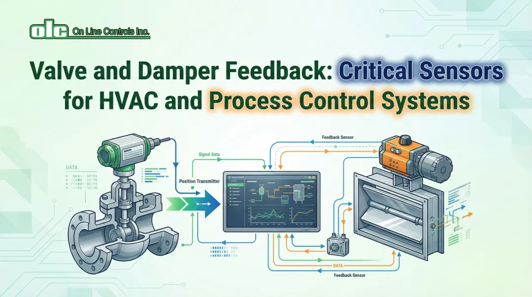
Feedback sensors are devices that convert the physical position, speed, or force of crane and hoist components into electrical signals. Control systems use these signals to regulate motor operation with precision.
These sensors solve the challenge of "blind" motor control. Without position feedback, operators cannot achieve repeatable, precise load placement or prevent dangerous overtravel conditions.
What feedback sensors are NOT:
- Not limit switches (which only signal endpoints, not continuous position)
- Not load cells alone (which measure weight but not position)
- Not the motor controllers themselves (they're the "eyes" that tell controllers where equipment actually is)
Why Feedback Sensors Remain Critical
Despite advances in automation, feedback sensors remain essential because crane operations are safety-critical. OSHA 1910.179 explicitly requires limit switches and overtravel protection. ISO 10245-1 specifies requirements for motion limiters and indicating devices.
Sensor failure can result in load drops, collisions, or structural damage. This makes redundant, reliable feedback systems both a regulatory and operational necessity.
When limit switches fail to operate properly during daily tests, OSHA regulations classify this as a critical safety hazard. Equipment must be shut down immediately, and supervisors notified.
How Do Feedback Sensors Work in Heavy Equipment?
Feedback sensors operate within a closed-loop control system where continuous position monitoring enables real-time motor adjustments to achieve precise load handling.
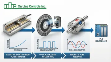
Signal Generation
When the crane bridge moves, hoist drum rotates, or trolley travels, the sensor's internal mechanism changes its electrical output in proportion to position or speed:
- Resistive track sensors (potentiometers) vary resistance as a wiper moves along a conductive element
- Optical disk sensors (encoders) generate digital pulses as a patterned disk rotates past a light source
- Magnetic pole sensors (resolvers) produce sine/cosine voltage signals that vary with shaft angle
Activation modes vary by sensor type:
- Continuous analog signals provide voltage or resistance changes proportional to position
- Digital pulse trains deliver encoder counts summed by controllers to determine distance
- Absolute position sensors output unique digital codes upon power-up without homing
These signals feed directly into the controller's feedback loop.
High-performance sensors achieve cycle times as fast as 1 millisecond. Advanced servo drives update position loops every 0.25 to 2 milliseconds—speeds that enable real-time response to load disturbances and operator commands.
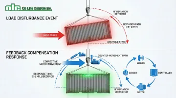
Feedback Loop Processing
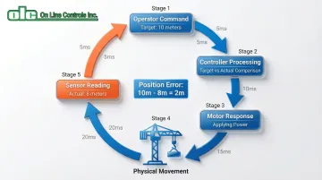
The controller continuously compares the sensor's "actual position" signal against the operator's commanded "target position." Any difference—called "position error"—triggers a proportional motor response to close the gap.
Here's how it works during operation:
If the load needs to move 10 meters but the sensor reports only 8 meters traveled, the controller maintains motor power. The sensor approaches 10 meters. The controller reduces motor speed for smooth deceleration and precise stopping.
This continuous adjustment cycle happens dozens of times per second.
Feedback loop speed affects critical performance variables:
- Positioning accuracy (how close the load stops to the target)
- Response time to load disturbances (wind, inertia, uneven weight)
- Ability to compensate for mechanical issues like cable stretch or gearbox backlash
Dynamic Compensation
When external forces affect the load—wind, inertia, or uneven weight distribution—continuous feedback allows the controller to detect unintended movement and apply corrective motor action. Advanced systems use multi-axis feedback to minimize load sway during travel and positioning.