Introduction: The Critical Role of Position Feedback in Control Systems
Many HVAC and industrial process control systems struggle with inefficiencies stemming from a critical gap: the disconnect between commanded positions and actual valve or damper positions. While 64% of HVAC controllers utilize closed-loop feedback mechanisms, only 25% achieve "excellent" performance ratings, with half rated as merely "fair" or "poor." This performance gap costs facilities thousands in wasted energy and compromised process control.
Position feedback sensors bridge this gap by providing real-time verification that valves and dampers actually reach their commanded positions. Without this feedback loop, control systems operate blind.
They cannot compensate for mechanical friction, pressure differentials, or actuator drift that prevent devices from reaching their setpoints.
Two related but distinct technologies serve different functions in control systems:
- Valve positioners actively control valve position by adjusting pneumatic pressure to the actuator
- Position feedback sensors passively monitor and report position to control systems
This article focuses on position feedback sensors, the critical monitoring devices that enable precise closed-loop control across HVAC damper systems and industrial valve applications.
TLDR: Key Takeaways on Valve and Damper Feedback Systems
- Position feedback closes the control loop by verifying actual device position matches controller commands
- Potentiometric sensors deliver ±2% accuracy at lower cost; digital encoders offer 25-bit resolution
- Digital encoders suit precision applications requiring sub-degree positioning accuracy
- Industrial installations benefit from 4-20mA current loops with superior noise immunity
- 0-10V voltage signals work well for shorter HVAC distribution runs
- Match environmental ratings to operating conditions—temperature range, IP protection, vibration tolerance
- Quality sensors deliver 10-20 year lifespans with annual calibration verification
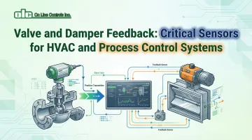
What is Valve and Damper Position Feedback?
Position feedback continuously monitors and reports the actual position of a valve or damper actuator to a control system. This real-time data enables closed-loop control, where the controller compares actual position against the commanded setpoint and makes corrections when needed.
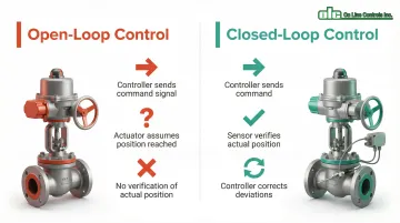
The difference between open-loop and closed-loop control is fundamental. Open-loop systems send a command signal and assume the device reaches target position—risky when mechanical friction, varying pressures, or actuator wear exist.
Closed-loop systems verify actual position, letting the controller compensate for these real-world obstacles.
Why Feedback Matters
Position feedback enables control systems to detect and correct several common failure modes:
- Sustained oscillations around setpoints waste energy and accelerate wear. Cascaded control loops using position feedback reduce hunting by linearizing system dynamics
- Valves and dampers shift position over time due to vibration, thermal expansion, or wear
- High differential pressures can prevent actuators from reaching commanded positions
- In VAV systems, failed static pressure sensors break the control loop, causing fans to oscillate and disrupt airflow
Applications Across Industries
Position feedback serves critical functions in both HVAC and industrial process control:
HVAC Systems: Damper position feedback ensures proper airflow distribution in VAV systems, economizer control, and mixed-air applications. Accurate damper positioning directly impacts energy efficiency and occupant comfort.
Industrial Process Control: Valve position feedback maintains precise control of steam, chemicals, water, and other process fluids in manufacturing, pharmaceutical production, and water treatment facilities. Feedback compensates for varying process conditions and mechanical wear in safety-critical applications.
Integration with Control Systems
Position feedback sensors integrate seamlessly with modern automation platforms:
- Building Automation Systems (BAS): BACnet and LonWorks protocols enable standardized sensor-to-controller communication
- Distributed Control Systems (DCS): HART, Modbus, and Foundation Fieldbus protocols provide real-time position data
- Programmable Logic Controllers (PLCs): Analog and digital inputs accept position signals for automated sequences
Types of Position Feedback Sensors
Position feedback sensors provide real-time data on valve and damper positioning, enabling precise process control in industrial and HVAC applications. The global position sensor market will reach $18.53 billion by 2034, with commercial HVAC systems accounting for 45.25% of market revenue and control sensors comprising 39.14% of this segment.
Potentiometric Position Sensors
Potentiometers function as variable resistors, with a wiper that moves along a resistive element to produce an output proportional to position.
As the actuator shaft rotates or extends, the wiper changes its position on the resistive element, altering the electrical resistance between terminals.
Rotary Potentiometers: Designed for rotary actuators on butterfly valves, ball valves, and dampers. Standard HVAC actuators typically feature 95° rotation angles, while industrial rotary potentiometers offer ranges from 15° to 360°.
Linear Potentiometers: Used with sliding-stem actuators on globe valves and linear damper operators. Stroke lengths range from 1 inch (25.4 mm) to 12 inches (304.8 mm) for industrial applications.
Accuracy and Specifications: Potentiometric sensors typically deliver ±2% linearity, suitable for general HVAC applications. Nominal resistance tolerance is typically ±5%, with minimum resolution of 1%.
Motorized Potentiometers: Applications requiring both position control and feedback use motorized potentiometers that combine a precision potentiometer with a motor and geartrain in a single assembly.
Dual-gang configurations provide one section for control and another for position feedback, enabling closed-loop positioning systems. These devices offer exceptional durability, with conductive plastic models rated for up to 50 million turns and wirewound versions providing 2 million turn life expectancy. Manufacturers like On Line Controls produce motorized potentiometers specifically engineered for demanding industrial process control applications.
Voltage Divider and Current Output Sensors
Output signal type determines sensor compatibility with control systems and transmission distance capabilities.
Voltage Output Sensors (0-10V or 0-5V):
- Common in HVAC applications due to lower cost and simple integration
- Compatible with standard analog control inputs
- Restricted to short cable runs (under 100 feet)
- Vulnerable to voltage drops and EMI over distance
Current Loop Sensors (4-20mA):
- Industry standard for industrial automation due to superior noise immunity
- Current remains constant throughout circuit, eliminating wire resistance effects
- Inherent error detection: 0 mA indicates line break or fault
- Suitable for long transmission distances (1,000+ feet)
- Ideal for electrically noisy environments with motors and VFDs
Digital Position Sensors and Encoders
Digital feedback technologies provide position data in binary or protocol-based formats, offering significant advantages over analog sensors for precision applications.
Absolute Encoders: Provide unique position codes at every point in the rotation, maintaining position information even after power loss. High-precision models offer ±20 arc seconds accuracy with 2048 lines, with resolution up to 25 bits (over 33 million discrete steps).
Incremental Encoders: Generate pulse trains as the shaft rotates, requiring the control system to count pulses from a known reference position. Accuracy scales with line count—512-line encoders provide ±60 arc seconds, while 2048-line models achieve ±20 arc seconds.
Key Advantages for Process Control:
- Superior resolution enables precision positioning in automated systems
- Built-in diagnostics detect sensor faults before failure
- Direct integration with fieldbus protocols (BACnet, Modbus, HART, Foundation Fieldbus)
- Reduced wiring complexity in networked installations
- Immunity to signal degradation over long distances
Fieldbus Protocol Compatibility:
- BACnet: Global standard for building automation, enabling interoperability between vendors
- HART: Bi-directional protocol with over 40 million installed instruments, overlaying digital data onto 4-20mA loops
- Modbus: Widely deployed master-slave protocol for industrial monitoring
- Foundation Fieldbus: Fully digital protocol enabling real-time closed-loop control between field devices

Analog vs. Digital Comparison
| Feature | Analog (Potentiometers) | Digital (Encoders) |
|---|---|---|
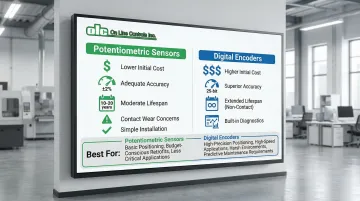
| Accuracy | Good (±2%), suitable for HVAC | Very high (25-bit resolution) |
| Installation | Simple, no signal conditioning | Requires decoding circuitry |
| Initial Cost | Lower | Higher |
| Durability | Moderate (contact wear) | High (non-contact designs) |
| Diagnostics | Limited | Built-in fault detection |
| Vibration Tolerance | Moderate | Excellent (10-50G shock rating) |
How Position Feedback Systems Work
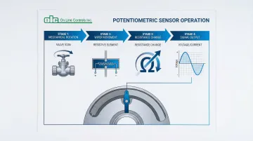
Position feedback systems follow a continuous signal chain that enables closed-loop control: mechanical position → sensor conversion → electrical signal → control system input → comparison with setpoint → corrective action.
Signal Conversion Process
The sensor converts mechanical position into an electrical signal using one of several methods:
Resistance-based (Potentiometric): The wiper position determines resistance between terminals. The control system applies a reference voltage across the resistive element, creating a voltage divider where output voltage is proportional to wiper position.
Current-based (4-20mA): Signal conditioning electronics convert the position-dependent resistance or voltage into a standardized current output. The 4 mA baseline represents 0% position, while 20 mA represents 100% position, with linear scaling between these points.
Digital (Encoders): Optical or magnetic sensors detect shaft position and convert it directly to digital codes transmitted via serial protocols or pulse trains.
Once the sensor generates an electrical signal, accurate control depends on proper calibration.
Calibration Procedures
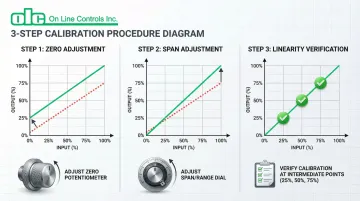
Calibration aligns the sensor's output with the physical position of the valve or damper through two key adjustments:
Zero Adjustment (Lower Range Value):
- Sets the sensor output at the 0% mechanical position
- For 4-20mA systems, aligns closed position with 4 mA output
- Produces a parallel shift of the input-output curve
- Performed with the actuator at its fully closed position
Span Adjustment (Upper Range Value):
- Sets the sensor output at the 100% mechanical position
- Aligns fully open position with 20 mA output (for current loops)
- Changes the slope of the input-output curve
- Performed with the actuator at its fully open position
Linearity Verification: After zero and span adjustments, check output at intermediate points (25%, 50%, 75%) to ensure linear tracking across the entire range. Non-linearity may indicate mechanical binding or sensor defects.
Signal Transmission Characteristics
| Signal Type | Best Distance | Key Advantages | Limitations |
|---|---|---|---|
| 4-20mA Current | Long runs (1000+ ft) | Wire resistance doesn't affect accuracy; highly resistant to EMI; self-diagnostic capability | Requires power supply; higher implementation cost |
| 0-10V Voltage | Short runs (<100 ft) | Simple wiring; lower cost; widely supported | Voltage drop over distance; susceptible to induced noise |
Current Loop Benefits: The 4-20mA standard excels in industrial environments because current remains constant throughout the circuit regardless of wire resistance. A reading of 0 mA indicates a wire break, while signals above 20 mA flag sensor faults—built-in diagnostics that voltage systems can't provide.
Voltage Signal Considerations: Best for short cable runs under 100 feet where wire resistance won't cause significant voltage drop. High-impedance inputs are susceptible to induced noise, so always use twisted-pair shielded cable in electrically noisy environments.
Wiring Best Practices: For multiple actuators on shared power runs, divide allowable wire length by the number of devices to prevent excessive voltage drop.
Always use copper twisted-pair conductors with proper grounding to minimize interference.
Signal Conditioning Requirements
Smart Actuators: Modern devices with Multi-Function Technology include built-in signal conditioning that can be reprogrammed on-site, allowing users to change feedback signal types (2-10V to 0-10V) or adjust scaling without hardware changes.
LVDT Sensors: Require stable AC excitation and signal conditioning amplifiers to convert raw AC output into standard DC voltage or current signals suitable for control system inputs.
Applications in HVAC and Process Control Systems
HVAC Damper Control Applications
Position feedback plays a critical role in energy-efficient HVAC operation, particularly in Variable Air Volume (VAV) systems where precise damper control directly impacts comfort and energy consumption.
VAV System Optimization: Trending damper position alongside zone temperature allows operators to verify that VAV boxes operate correctly.
This ensures dampers reach minimum settings before reheat activates, preventing simultaneous heating and cooling waste.
Static Pressure Reset: ASHRAE Guideline 36 recommends using zone damper positions to reset static pressure setpoints. By keeping at least one damper nearly wide open, fan speed can be minimized, significantly reducing fan energy consumption—often the largest HVAC electrical load.
Economizer Control: Outdoor air dampers require accurate positioning to maximize free cooling while maintaining minimum ventilation rates. Position feedback ensures dampers don't drift from commanded positions due to linkage wear or actuator issues.
ASHRAE 90.1-2022 mandates specific accuracy thresholds for sensors in economizer and damper control.
While the standard focuses on temperature (±2°F) and humidity (±5% RH) sensors, position feedback accuracy of ±2-5% is typical for HVAC applications to ensure proper airflow distribution.
Valve Control in Industrial Processes
Industrial process control demands higher accuracy and reliability than HVAC applications due to safety implications and product quality requirements.
Key applications include:
- Steam Control: Maintains consistent steam pressure and temperature in heating processes, pharmaceutical sterilization, and power generation
- Chemical Processing: Compensates for varying differential pressures in reactors, distillation columns, and blending operations where exact flow ratios are critical
- Water Treatment: Ensures proper chemical dosing, filtration rates, and distribution in municipal water and industrial wastewater systems
- Pharmaceutical Manufacturing: Provides documented proof that valve positions remain within validated ranges throughout FDA-regulated production runs
Performance Standards: ISA-75.13.01-2013 specifies test methods for evaluating valve control performance including hysteresis, linearity, deadband, and sensitivity. These metrics establish baseline expectations for feedback sensors in industrial control loops.
Integration with Modern Control Systems
Modern sensors offer direct BACnet or Modbus integration with Building Automation Systems. They communicate position values plus diagnostic data like sensor temperature, calibration status, and fault codes.
Industrial protocols such as HART and Foundation Fieldbus enable two-way communication. Control systems can remotely configure sensors, perform diagnostics, and receive detailed operational data beyond simple position readings.
Advanced Control Strategies: Position feedback enables sophisticated control methods including:
- Cascade control: Using position feedback as the inner loop to linearize valve response
- Feedforward control: Anticipating disturbances and adjusting valve position proactively
- Model predictive control: Using position data to validate process models and optimize multi-variable control
Safety and Compliance Applications
Safety Shutdown Systems: Position feedback verifies that emergency shutdown valves reach fully closed positions during safety events, providing documented proof for incident investigations.
Fail-Safe Positioning: Continuous monitoring detects when spring-return actuators fail to return to safe positions on loss of power or air supply.
Regulatory Compliance: FDA guidance on cGMP emphasizes data integrity principles—Attributable, Legible, Contemporaneous, Original, and Accurate. Electronic records of valve positions in critical process steps must meet these standards, shifting selection criteria from pure performance to include data security and auditability.
Audit Trail Capabilities: Digital position sensors with fieldbus connectivity provide timestamped position logs that satisfy regulatory requirements for documentation and traceability in pharmaceutical, food processing, and chemical manufacturing.
Selecting the Right Position Feedback Solution
Key Selection Criteria
Accuracy Requirements
Match sensor precision to your application demands:
- HVAC damper control: ±2-5% accuracy works for most installations
- Industrial throttling valves: ±1-2% accuracy recommended
- Precision process control: Digital encoders with 0.01% resolution or better
Environmental Conditions
Standard commercial sensors operate -22°F to 122°F (-30°C to 50°C). Industrial models extend to 185°F (85°C) storage.
Protection ratings matter:
- IP54/NEMA 2 for standard indoor applications
- IP65/IP67 for washdown or outdoor environments
- Industrial encoders withstand 10G at 10-2000 Hz vibration and 50G shock
- Stainless steel housings resist corrosive atmospheres in chemical processing
Physical Installation
Rotary sensors must match actuator travel (90°, 180°, 360°). Linear sensors need stroke length that accommodates full valve stem travel with margin for mechanical stops.
Plan for maintenance access during calibration and inspection.
Compatibility Considerations
Beyond sensor specifications, integration with existing equipment determines success.
Verify mechanical interface compatibility with existing actuators:
- Shaft diameter and coupling method
- Mounting hole patterns
- Sensor rotation/stroke matching actuator travel
Control system integration requires signal matching:
- Analog: 0-10V, 0-5V, or 4-20mA output
- Digital: BACnet, Modbus RTU/TCP, HART, or Foundation Fieldbus
- Input impedance compatibility
Retrofit projects face space constraints and existing wiring limitations. New installations offer flexibility to specify optimal sensor technology and proper wiring infrastructure.
Cost-Benefit Analysis
Basic potentiometers work well for:
- Standard HVAC damper control (±2% accuracy adequate)
- Budget-constrained projects with minimal environmental challenges
- Low cycle counts (fewer than 100,000 full cycles)
- Short wire runs where voltage signals remain reliable
Digital sensors justify their cost in demanding applications:
- Precision process control requiring <±1% accuracy
- High-vibration environments (pumps, compressors, mobile equipment)
- Long transmission distances or electrically noisy locations
- Systems needing diagnostic data and predictive maintenance
- Installations with existing fieldbus infrastructure
Digital encoders cost 2-3 times more initially. However, they deliver lower total cost in high-reliability applications through extended lifespan, reduced calibration needs, and predictive maintenance that prevents unplanned downtime.
Non-contact designs eliminate wear. Networked systems reduce installation labor.
Installation and Maintenance Best Practices
Installation Guidelines
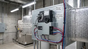
Mechanical Mounting:
- Align sensor shaft concentrically with actuator shaft to prevent side-loading and premature wear
- Use flexible couplings to accommodate minor misalignment
- Secure mounting bracket rigidly to prevent vibration-induced errors
- Ensure sensor can reach mechanical stops without binding or over-travel
Electrical Connections:
- Use shielded twisted-pair cable for all analog signals
- Ground shield at control panel end only (not both ends) to prevent ground loops
- Maintain minimum 6-inch separation from power wiring and VFD cables
- Follow NEC Article 250 requirements for grounding and bonding
- Label all connections clearly for future maintenance
Initial Calibration:
- Allow sensor to stabilize at ambient temperature before calibration
- Perform zero adjustment with actuator at fully closed position, then span adjustment at fully open position
- Verify linearity at 25%, 50%, and 75% positions to confirm accuracy across the travel range
- Document calibration settings and date for maintenance records
Common Installation Mistakes
- Improper grounding or failure to use twisted shielded pairs introduces signal noise and ground loops that corrupt position readings
- Mechanical misalignment between sensor components (like LVDT core and coil) causes friction, inaccurate readings, and premature failure
- Calibrating sensors in uncontrolled environments without adequate warm-up time creates baseline errors from temperature or humidity variations
- Undersized power wiring creates voltage drop that causes actuators to operate below rated voltage, resulting in slow response and incomplete travel
Preventive Maintenance Practices
Periodic Calibration Verification:
- Annual calibration checks for precision applications
- Verify zero and span points haven't drifted
- Check linearity across travel range
- Document results and compare to baseline
Regular inspections catch problems before they cause system failures.
Connection Inspection:
- Inspect terminal connections for corrosion or looseness quarterly
- Check cable insulation for damage, especially near moving parts
- Verify shield grounding remains intact
- Tighten mounting hardware that may loosen from vibration
Cleaning Procedures:
- Remove dust and debris from sensor housing
- Clean optical windows on encoder sensors
- Avoid solvents that may damage plastic housings or seals
- Ensure drainage holes remain clear on outdoor installations
Understanding sensor lifespan helps you plan replacements before failures occur.
Sensor Lifespan Considerations:
- Quality potentiometric sensors: 10-20 years typical lifespan with 100,000 full cycles and 2.5 million repositions
- Contactless encoders: Longer lifespans due to elimination of mechanical wear
- Motorized potentiometers: Premium models rated for 50 million turns
- Plan replacement based on cycle count, not just age
Failure Mode Recognition:
- Potentiometers: Erratic output or dead spots indicate resistive element wear
- Encoders: Sudden position jumps suggest optical contamination or damaged disc
- All types: Gradual drift indicates calibration loss; sudden offset suggests wiring fault
Frequently Asked Questions
What is a valve position potentiometer?
A valve position potentiometer is a variable resistor mechanically coupled to a valve actuator shaft that converts valve position into an electrical signal (resistance, voltage, or current) for monitoring by control systems. As the valve moves, a wiper travels along a resistive element, creating proportional resistance changes that represent actual valve position.
When should you use a valve positioner?
Use valve positioners when precise positioning is critical, when high differential pressures exceed standard actuator capabilities, or when fast response is needed. Unlike passive position feedback sensors that only report position, positioners actively control pneumatic pressure to achieve target positions.
What are the different types of valve positioners?
The three main types are pneumatic positioners (P-to-P) that receive and output pneumatic signals, electropneumatic positioners (I-to-P) that convert electronic current signals into pneumatic output, and digital smart positioners that use microprocessors for advanced features like auto-calibration, diagnostics, and digital communication protocols.
Does the orientation of a valve position potentiometer matter?
Orientation matters for some designs but not others. Gravity-dependent sensors may experience accuracy shifts in non-standard orientations, while orientation-independent designs maintain accuracy regardless of mounting position. Always follow manufacturer installation guidelines for approved mounting positions.