Closing the loop between a PLC and a pressure regulator is the logical solution. The challenge is that the path from "wired up and running" to "actually stable" involves four distinct stages, each with its own failure modes. Signal type mismatches, poor analog scaling, and PID parameters copied from the wrong application are far more common culprits than complex programming errors.
This article walks through each stage — signal mapping, wiring, PLC program configuration, and PID tuning — with the specific details that determine whether the integration actually improves tubing OD consistency.
TL;DR
- Closing the loop between a PLC and pressure regulator enables automatic, repeatable tubing OD control
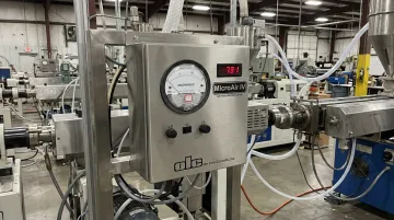
- The regulator must accept an automation-compatible signal — OLC's MicroAir IV takes a 0–10 VDC analog input directly from a PLC
- Integration follows four stages: signal mapping, wiring, PLC program configuration, and PID tuning
- The most common failure points are incorrect signal scaling, poor grounding, and aggressive PID gains
- Ultra-low pressure tubing extrusion (often 0.5 to 5 inches of water) requires specialized regulators; standard industrial pneumatic regulators will not work
What You Need Before Integrating a Pressure Regulator with Your PLC
Gaps discovered mid-installation cause the most costly delays. Confirm these requirements before touching a single wire.
Hardware and Signal Compatibility
Not every pressure regulator accepts a PLC analog signal out of the box. For PLC integration, you need a regulator with a built-in analog input or a compatible actuator interface.
OLC's MicroAir IV is purpose-built for this: it accepts a 0–10 VDC input that directly controls pressure in Linear mode, where the analog signal maps proportionally from near-zero to full-scale pressure. An internal switch disables the front panel controls when operating via PLC, so no additional actuator is required.
Confirm these hardware items before proceeding:
- PLC analog output module supports 0–10 V (or 4–20 mA, depending on your regulator)
- Module resolution — common options range from 12-bit (4,096 counts) to 16-bit (65,536 counts); verify your specific catalog number
- Regulator's rated pressure range covers the application's working pressure
- For internal air support in tubing extrusion, working pressures commonly fall between 0.5 and 5 inches of water — standard industrial pneumatic regulators, which typically start at 2 PSI or higher, cannot operate reliably here
Feedback and Safety Readiness
Two feedback approaches are common — choose based on how tightly you need to control OD:
- Pressure transducer downstream of the regulator — simpler to implement, reflects supply pressure
- OD gauge signal (from LaserLinc, Zumbach, or similar) fed back to the PLC — tighter OD control, but adds transport delay to the loop
Whichever you select, confirm the transducer's rated pressure range matches the application's working window. A transducer ranged at 0–100 PSI will have almost no usable resolution at 2 inches of water.
Before powering up, work through these electrical safety checks:
- Verify the PLC analog output's load rating matches the actuator or regulator input impedance
- Confirm all wiring meets facility electrical standards
- Check for isolation requirements between the PLC output circuit and the regulator input
How to Integrate a Pressure Regulator with Your PLC on an Extrusion Line
Step 1: Map the Signal Interface Between PLC and Regulator
Start by documenting the complete signal chain before any physical work begins:
PLC analog output → signal cable → regulator input → pressure output
This is where most integration mismatches originate. The point where the electrical signal ends and mechanical or pneumatic action begins must be clearly identified, because that transition determines what signal type, range, and polarity you need at every point upstream.
Confirm these details for your specific hardware:
- Output type on the PLC module: voltage (0–10 V) or current (4–20 mA)
- Whether the output is sourcing or sinking
- Whether the signal range aligns with the regulator's input range
- The PLC module's maximum load — Omron NX-series current outputs, for example, are rated to 600 ohms for 2-point units and 350 ohms for 4-point units
For the MicroAir IV, the signal path is straightforward: the 0–10 VDC output from the PLC maps directly to the regulator's analog input. No intermediate transducer or actuator is required. Record this chain in your project documentation before moving to wiring.
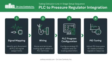
Step 2: Wire the Analog Output to the Regulator Input
Cable selection and routing:
- Use shielded, twisted-pair cable from the PLC analog output terminal to the regulator input
- Ground the cable shield at one end only (typically the PLC end) to prevent ground loops
- Route analog signal cables away from motor leads, VFD output cables, and AC power conductors; where crossings are unavoidable, cross at 90 degrees
- Maintain at least 12 inches of separation from AC power lines carrying 20A or more when not in conduit
Before connecting to a live PLC output:
- Verify zero short circuits between signal conductors and the cable shield using a multimeter
- Confirm the regulator input impedance is within the PLC module's rated load range
- Check terminal polarity against the manufacturer's wiring documentation; floating signal commons are a frequent cause of erratic behavior after initial power-up
For the MicroAir IV's power supply requirements, the unit operates on 110/220 VAC (dual selectable). Contact OLC at 978-562-5353 for terminal-level wiring diagrams specific to your configuration.
Step 3: Configure the PLC Program for Closed-Loop Pressure Control
Analog input scaling block (feedback signal):
- Convert the raw signal from your pressure transducer or OD gauge into engineering units (inches of water or PSI)
- Set low-scale and high-scale values to match the transducer's rated range, not the full instrument range — this maximizes resolution at the working pressure
Resolution matters here: a 12-bit output scaled to 0–1 PSI gives approximately 0.000244 PSI per count (0.00676 inches of water). Scale that same output to 0–10 PSI and you're left with only ~41 counts across a 0.1 PSI band — too coarse for precise diameter control.
PID function block configuration:
- Reference input: pressure setpoint (in engineering units)
- Process variable: scaled feedback signal
- Control variable: analog output to regulator
- Output limits: set minimum and maximum to prevent driving the regulator below its mechanical minimum or above the line's pressure ceiling
PID execution timing:
Place the PID function block in a cyclic interrupt task so it executes at a constant, configured interval. Siemens explicitly requires this for PID_Compact; Rockwell's PIDE instruction supports Periodic mode for the same purpose. Consistent sample timing is not optional: variable scan execution corrupts integral calculations.
Confirm direct vs. reverse acting before enabling automatic mode: if increasing the PLC output increases air pressure, configure direct action. Verify this against actual regulator behavior during manual testing in Step 4.
Step 4: Tune the PID Loop and Validate the Integration
Start in manual mode — always:
Before enabling automatic control, run the line with the PLC in manual output mode. Command the regulator to several positions across its range and confirm it follows correctly. If the regulator does not respond predictably to manual commands, there is a wiring or configuration error that closed-loop control will not fix. Automatic mode will only hide the problem until pressure spikes, OD drifts out of tolerance, or an alarm trips.
Initial conservative gain settings:
- High proportional band (low gain)
- Long integral time
- No derivative action initially
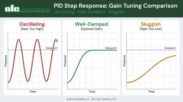
Step response test procedure:
- With the loop in automatic mode, make a small, controlled setpoint step (5–10% of range)
- Record how quickly and smoothly the process variable responds
- Classify the response: oscillating (gain too high), sluggish (gain too low), or well-damped
For a structured starting point, the Ziegler-Nichols reaction curve method uses the open-loop step response to calculate Kc, Ti, and Td from measured process gain, time constant, and dead time. Starting from measured values means your first tuned parameters are in the right ballpark — fewer destructive oscillations before the loop stabilizes.
Production validation:
Once the loop holds steady under controlled conditions, put it through real operating stress. Log pressure variation before and after integration. Confirm stability holds during line speed changes, material temperature shifts, and spool transitions. This baseline documents the actual improvement and gives you a reference point if performance degrades later.
Key Parameters That Affect Integration Performance
Even a correctly wired and programmed integration will underperform if these variables are poorly selected.
Signal Resolution and Scaling
A 12-bit analog output provides 4,096 steps. If the full output range maps to 0–10 PSI, each step equals ~0.0024 PSI (0.067 inches of water). At a working pressure of 2 inches of water, that resolution is barely acceptable. Map the same output to 0–0.5 PSI and each step becomes ~0.000122 PSI — roughly 15 times finer.
Insufficient scaling resolution causes pressure to "step" rather than vary smoothly. The result appears in OD measurements as a repeating diameter pattern rather than random variation.
Scale the PLC analog output to the narrowest practical pressure window the application requires.
PID Gain Settings and Dead Time
Control Engineering confirms that dead time directly limits how aggressively a loop can be tuned — more dead time requires lower gain and longer integral time to remain stable.
For internal air pressure control:
- Proportional gain too high: loop oscillates around setpoint
- Proportional gain too low: slow disturbance rejection when line speed or material viscosity shifts
- Feedback transducer close to the regulator: lower dead time, allows tighter tuning
- Feedback transducer close to the die: more accurate reading of actual internal pressure, but adds transport delay
No universal starting gain exists for this application. Use the step response test from Step 4 to measure your actual dead time, then calculate gains from that measurement.
Regulator Mechanical Response Time
The MicroAir IV responds to a 50% full-scale step in less than 0.1 second (typically 20 ms). That response speed is fast enough to keep pace with any PLC scan rate on a tubing extrusion line.
If you are using a slower actuator (a motorized potentiometer with full-range travel in 30+ seconds, for example), the PID integral term will wind up during the mechanical lag and cause overshoot when the actuator finally catches up.
In that case, the integral time must be matched to the actuator's actual travel speed, not the process dynamics.
Common Mistakes When Integrating Pressure Regulators with a PLC
Wiring a 0–10 V PLC output to a 4–20 mA actuator won't cause immediate damage, but will produce erratic, unpredictable behavior. Always confirm signal type compatibility before the first live test.
Mapping 0–100% output to 0–10 PSI when your process runs at 0–0.5 inches of water wastes nearly all usable resolution. Scale the output range to the narrowest practical window.
If the regulator doesn't respond correctly to manual commands, enabling PID mode won't surface the problem — it drives the actuator to its limit chasing an error it can never correct. Validate manual response first.
Air is roughly 1,000× more compressible than hydraulic oil (bulk modulus ~1.4 × 10⁶ Pa vs. ~1.7 × 10⁹ Pa for oil), which means an air pressure loop responds far faster and carries far less inertia. PID gains tuned for a gear pump or melt pressure loop will almost always oscillate when applied to internal air control.
Standard industrial pneumatic regulators typically bottom out at 2 PSI — far too coarse for sub-1 PSI extrusion applications. OLC's MicroAir line holds pressures below 1 inch of water (0.036 PSI), and the 0–0.25" of water MicroAir I has been validated stable at 0.05" of water. A general-purpose regulator in the same application will wire in cleanly but be practically uncontrollable.
Conclusion
Integrating a pressure regulator with a PLC on a tubing extrusion line follows a defined four-stage sequence: signal mapping, wiring, PLC program configuration, and PID tuning. Each stage must be completed correctly before advancing to the next. Skipping the manual validation step before enabling automatic mode, or borrowing PID gains from an unrelated application, produces instability that is time-consuming to diagnose.
The hardware foundation matters equally. A regulator rated for the application's actual pressure range — not a general-purpose industrial unit repurposed for sub-1 PSI work — determines whether closed-loop integration achieves fine OD control or only approximates it.
Getting signal scaling right and placing the feedback transducer thoughtfully determines how much of the loop's potential resolution actually reaches the tubing.
For application-specific guidance on integrating OLC's MicroAir IV with your PLC platform, contact On Line Controls at 978-562-5353 or olc@onlinecontrols.com.
Frequently Asked Questions
What are the main types of pressure regulators used in extrusion systems?
Melt pressure regulators control high-pressure polymer flow upstream of the die, typically operating in the hundreds of PSI range. Internal air pressure regulators are a separate category: ultra-low pressure devices that maintain the air pressure supporting tubing geometry during free extrusion, often operating below 5 inches of water. PLC integration requirements, signal types, and tuning approaches differ significantly for each.
What is the function of a melt pump in an extrusion system?
A melt pump is a gear-driven, constant-volume device installed between the extruder and die that isolates die pressure from screw fluctuations. It controls melt pressure , which is a separate function from the internal air pressure regulation used to maintain tubing OD.
What is the typical air pressure used for internal tubing support during extrusion?
Internal air support pressures for free-extruded plastic tubing are extremely low — typically 0.5 to 5 inches of water (0.018 to 0.18 PSI) for medical and fine-bore tubing. This ultra-low range requires specialized regulators. OLC's MicroAir units can hold stable pressure below 1 inch of water, with validated performance down to 0.05 inches of water on the lowest-range models.
Can a motorized potentiometer be used to connect a pressure regulator to a PLC?
Yes. A motorized potentiometer converts a PLC analog signal into a mechanical adjustment of a regulator's control knob — a practical interface for regulators without a built-in analog input. OLC manufactures standalone motorized potentiometers with adjustable travel speeds for this purpose. The MicroAir IV eliminates the need for this approach by accepting a 0–10 VDC signal directly.
What PLC analog output signal type works best for controlling a pressure regulator on an extrusion line?
According to Fluke, 4–20 mA is the most widely used analog signal in industrial process control because current loops are less susceptible to electrical noise and maintain signal integrity over long cable runs. Where the regulator accepts it, 4–20 mA is preferred over 0–10 V in environments with nearby VFDs or motor drives. The MicroAir IV uses 0–10 VDC input; its output option supports both 0–10 VDC and 4–20 mA for closing the feedback loop to the PLC.