Plastic Pipe Extrusion: How the Line Works and How to Keep OD & Wall on Spec - Google Drive
Plastic pipe extrusion looks simple from the outside. Melt goes in. Pipe comes out. The real work is keeping dimensions consistent once the line is running, because small shifts in sizing conditions, cooling, or line speed can show up as OD drift, wall variation, or ovality.
In this guide, we’ll walk through the extrusion line in one clean pass, then focus on the few variables that actually control pipe size and stability, plus what to check first when the output starts to move.
Key Takeaways
Plastic pipe extrusion forms pipe by pushing molten polymer through a die, then sizing and cooling it to lock in the final dimensions.
A typical line has five main stations: die/tooling, sizing/calibration, cooling, haul-off/puller, and cutting or coiling.
The variables that most affect OD, wall thickness, and ovality are line speed vs puller draw, sizing vacuum/air support stability, cooling consistency, and tooling/alignment condition.
When dimensions drift, check first: sizing conditions (vacuum/pressure and alignment), cooling stability, then puller speed/draw before assuming the material is the issue.
How does Plastic Pipe Extrusion Work?
Plastic pipe extrusion takes polymer pellets, melts them, and pushes the melt through a die to form the basic pipe shape. From there, the line stabilizes the shape in sizing/calibration, removes heat in cooling, and uses the haul-off to pull the pipe through at a controlled rate. Finally, the pipe is cut to length or coiled, depending on the product.
In pipe terms, “quality” is mostly dimensional and surface-driven. The big four are outside diameter (OD), wall thickness, ovality/out-of-round, and surface finish. If any of those move, it usually traces back to sizing stability, cooling consistency, puller control, or tooling condition.
The Pipe Extrusion Line: What Each Station Does
Think of the line as five stations with five jobs; each one influences dimensions differently, so knowing where you are in the chain makes troubleshooting faster.
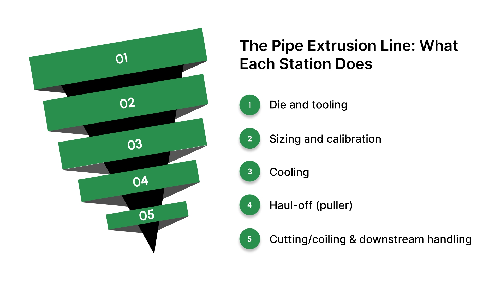
Die and tooling
This is where the melt is formed into the initial pipe shape. Tooling design and condition influence how evenly the melt flows, which affects dimensional balance before the pipe ever reaches sizing.
Sizing and calibration
This station stabilizes the pipe and establishes the target outside diameter and roundness. If OD or ovality drifts, this is often the first place to look because it is where the shape is held and guided while still soft.
Cooling
Cooling removes heat so the pipe “sets” and holds its dimensions. Inconsistent cooling shows up as gradual dimensional movement, ovality changes, or surface issues, especially when conditions vary along the line.
Haul-off (puller)
The puller controls how fast the pipe is drawn through the line. Changes in puller speed and grip behavior affect draw, which can influence wall thickness and dimensional stability when the rest of the line stays constant.
Cutting/coiling and downstream handling
This is where the pipe is cut to length or coiled and packaged. Downstream handling does not usually create true dimensional drift, but poor handling can affect finish, marking, or consistency in cut length and presentation.
Once you know which station sets shape, which one locks size, and which one controls draw, it becomes much easier to trace OD, wall, or ovality changes back to the right adjustment point.
Quick line map: station → what it sets → what drifts → what to check
Use this table as a fast “where do I look?” map when OD, wall, or roundness starts moving during a run.
Line station | What it primarily controls | What you see when it’s off | First thing to check |
|---|---|---|---|
Die / tooling | Initial shape and melt flow balance into the line | Early imbalance, unstable output that sizing can’t fully “save,” inconsistent finish | Tooling condition, alignment, contamination/wear, temperature consistency |
Sizing/calibration | OD and roundness while the pipe is still soft | OD drift, ovality changes, “won’t hold size” behavior | Vacuum/air support stability, calibrator condition/alignment, leaks, and sealing surfaces |
Cooling | How quickly do dimensions get locked in | Gradual size movement, ovality changes, surface issues that come and go | Water temperature stability, flow consistency, tank levels, and coverage |
Haul-off / puller | Line speed and draw through the process | Wall variation, size shifts tied to speed changes, slip marks | Puller speed stability, belt/track condition, and grip, synchronization with upstream settings |
Cutter/coiler | Length/handling consistency and finish presentation | Length inconsistency, marking/scuffing, handling defects | Cutter timing/setup, downstream tension/handling, guides, and supports |
The goal is not to adjust everything at once; it’s to identify the station most likely driving the symptom, verify the basics there, and only then make a controlled change.
What actually controls pipe size and stability
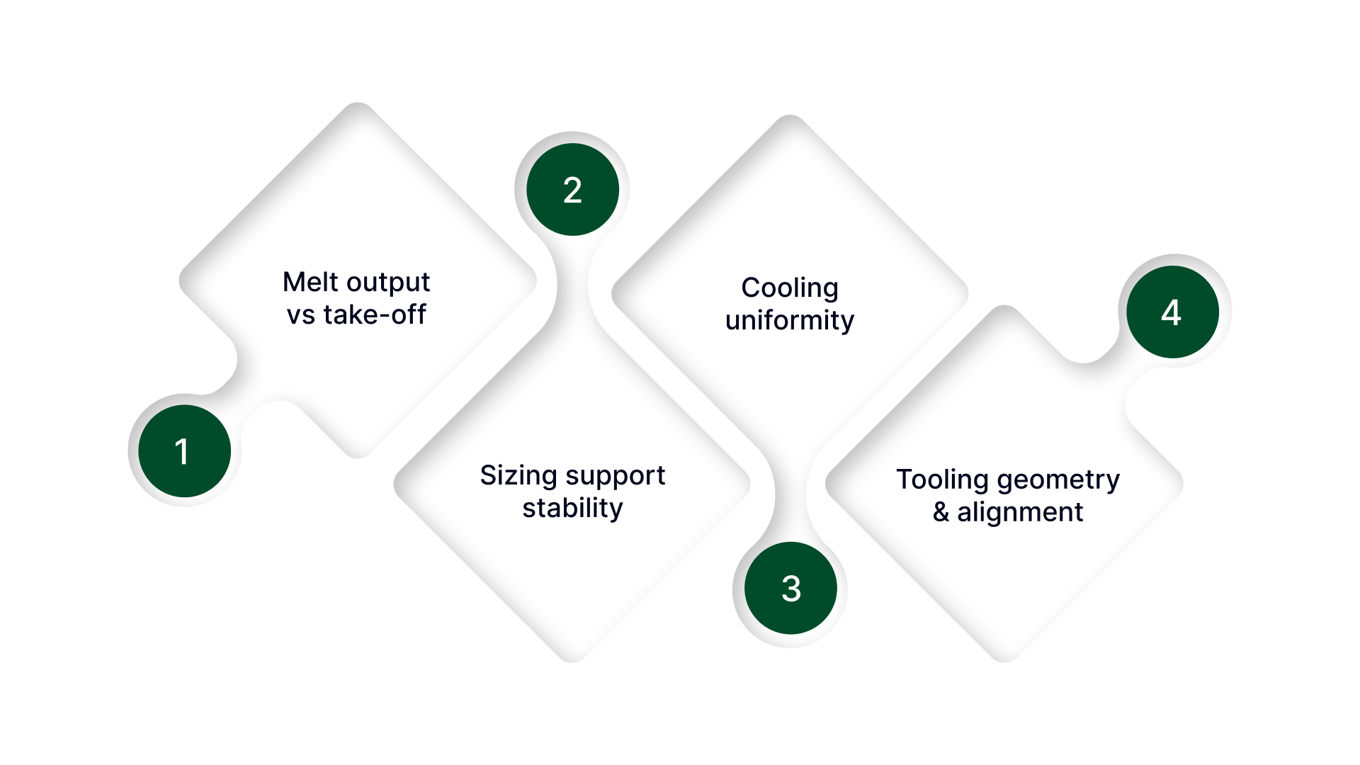
If the line stations are the hardware, these are the levers that decide whether dimensions stay put from minute to minute.
Melt output vs take-off (draw balance)
Pipe size depends on a steady balance between how much material is being delivered and how aggressively the line is pulling it away. When that balance shifts, the pipe can change size even if nothing “looks” different on the line.
This is why dimensional changes often track with speed changes, startup transitions, or small throughput swings.
Sizing support stability (vacuum/air + sealing)
The sizing stage only works when the support conditions are steady. If the vacuum level, air support, or sealing performance varies, the pipe sees a different forming force over time.
That shows up as gradual OD movement or roundness changes that are hard to correct with one adjustment.
Cooling uniformity (temperature + flow + coverage)
Dimensions don’t become permanent until the pipe is cooled consistently. Uneven or changing cooling conditions can lock one section faster than another, which drives slow drift and can bias roundness.
Stable water temperature, stable flow, and consistent coverage matter more than “more cooling.”
Tooling geometry and alignment
Even a small mechanical bias can push the pipe away from true round. Wear, buildup, off-center alignment, or uneven support tends to show up as ovality, uneven wall distribution, or a line that never feels repeatable across runs.
When these four levers stay stable, the line stops “wandering,” and OD, wall, and roundness become repeatable instead of something you constantly chase.
Common problems: symptom → first suspect
This table helps you go from “what you’re seeing” to the most likely first suspect, without bouncing between stations or changing multiple settings at once.
Symptom pattern | First suspect |
|---|---|
OD drifts slowly over time (no major setting changes) | Support or cooling stability |
OD changes right after a line speed change | Draw balance (melt output vs take-off) |
OD is stable at startup, then wanders after the line “settles.” | Thermal stabilization across sizing/cooling |
Wall varies along the length (thick/thin zones down the pipe) | Puller stability or output consistency |
The wall is uneven around the circumference (one side thicker) | Alignment/centering (tooling + sizing) |
Ovality is consistent and repeatable run-to-run | Mechanical geometry (wear, centering, sizing, alignment) |
Ovality comes and goes during the run | Unstable support or uneven cooling coverage |
Surface marks repeat in the same location | Contact/handling points (guides, puller surfaces, supports) |
Surface finish changes with cooling conditions | Cooling uniformity |
Bubbles/voids are persistent | Material handling/moisture or air entrainment upstream |
Bubbles/voids are intermittent | Leaks/instability (feed or temperature swings) |
Once you identify the symptom pattern, verify the simplest checks tied to that suspect first, then make one controlled change and watch the result before moving on.
If your checks are solid but the line still ‘behaves differently’ after a resin change, the material family is usually why.
PVC vs PE/PP: Why the Same Settings Behave Differently
PVC and polyolefins (PE/PP) can run on similar-looking lines, but they don’t behave the same once you’re trying to hold tight dimensions.
The biggest practical difference is how each material responds to heat removal and how quickly the pipe becomes “self-supporting” as it cools.
That changes how sensitive the process feels to cooling stability and support conditions.
Here’s what operators typically notice:
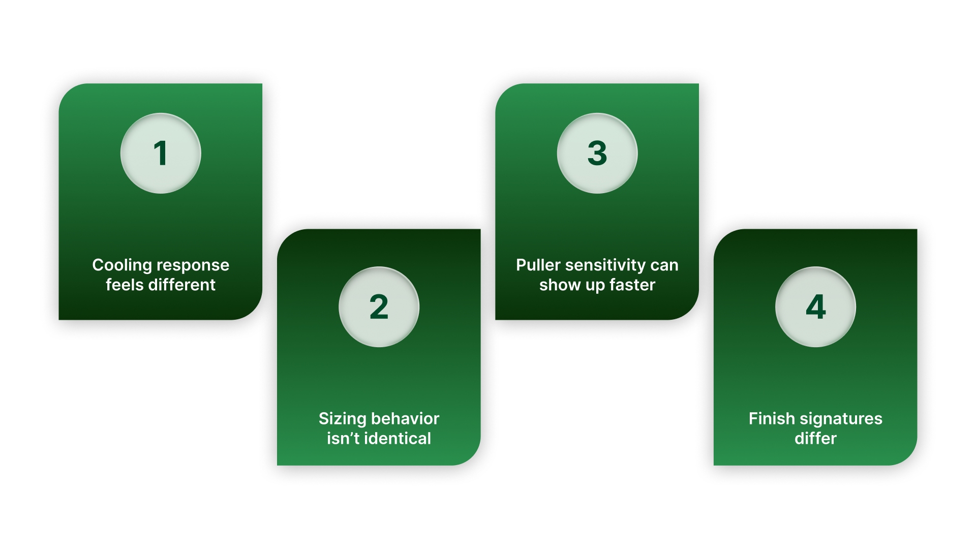
Cooling response feels different. One material may tolerate small cooling swings, while another shows dimensional movement or finish changes sooner when water temperature or flow varies.
Sizing behavior isn’t identical. Some materials “take” sizing more easily, while others are more sensitive to support stability and alignment when the pipe is still soft.
Puller sensitivity can show up faster. Changes in take-off speed may translate into size or wall changes more quickly on certain materials, especially during transitions.
Finish signatures differ. The same cooling and handling setup can produce different surface results depending on the resin family and how it freezes in the line.
The resin and the process window change, but the control logic stays the same: keep support conditions steady, keep cooling uniform, and keep draw balanced with melt delivery.
If you’re chasing drift, the fastest wins usually come from improving consistency in support and pressure control, not from constant setpoint tweaks. That’s where On Line Controls fits.
Where On Line Controls fits
No matter the resin, holding OD and roundness comes down to steady sizing support and predictable low-pressure behavior. That’s when pressure control hardware becomes a practical requirement, not an add-on.
On Line Controls focuses on low-pressure regulation and control used in extrusion and process-air applications. In practical terms, that means equipment designed to help maintain stable, repeatable low pressures where small swings can show up in the product.
We also publish extrusion-focused technical resources, which are useful when you are troubleshooting a drift problem and need a clearer model of what the air system is actually doing.
When you’re matching pressure control to an extrusion line, focus on:
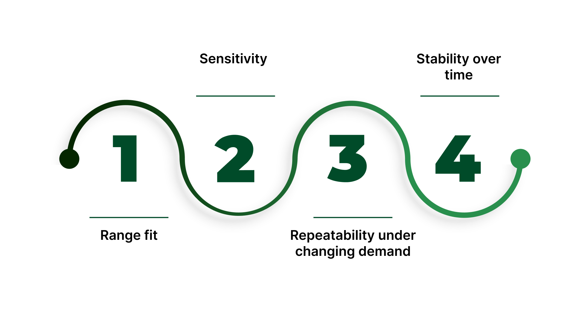
Range fit: pick a range where your normal operating point sits comfortably, not at the edge.
Sensitivity: You should be able to make small adjustments without “jumping” past the sweet spot.
Repeatability under changing demand: expect the system to see flow changes during real operation, not just at idle.
Stability over time: the setting should hold without constant touch-ups.
If you want to tighten up low-pressure stability in sizing or support air, review On Line Controls’ pressure-control/regulator options and get in touch to confirm range and fit for your setup.
Conclusion
Plastic pipe extrusion stays predictable when you treat it like a stability problem, not a guessing game. Start by understanding what each station is responsible for, then use the quick maps to narrow the issue based on what you’re seeing.
When you focus on draw balance, steady sizing support, uniform cooling, and true alignment, OD, wall, and roundness stop drifting and become easier to hold run after run.
FAQs
What is plastic pipe extrusion?
Plastic pipe extrusion is a manufacturing process that melts polymer and pushes it through a die to form a continuous pipe, then uses sizing and cooling to lock in the final dimensions before cutting or coiling.
What equipment is used in a pipe extrusion line?
A typical pipeline includes an extruder, die/tooling, sizing/calibration equipment, cooling tanks, a haul-off/puller, and a cutter or coiler. Many lines also include downstream handling and measurement systems, depending on the application.
How do you control pipe OD during extrusion?
OD is mainly controlled by stable sizing conditions and consistent cooling, with line speed and draw balance playing a major role. If OD moves, start by checking sizing support stability, cooling stability, and then puller behavior.
What causes wall thickness variation in extruded pipe?
Wall variation commonly comes from changes in draw balance, puller stability, melt delivery consistency, or alignment issues that bias flow and support. The pattern matters—variation along the length often points to stability issues, while circumferential bias often points to alignment/centering.
What is vacuum sizing (calibration) in pipe extrusion?
Vacuum sizing (calibration) is the step where the hot pipe is supported and formed to the target outside diameter and roundness using a calibrator. Vacuum and sealing help hold the pipe against the sizing surfaces while it is still soft enough to be shaped.