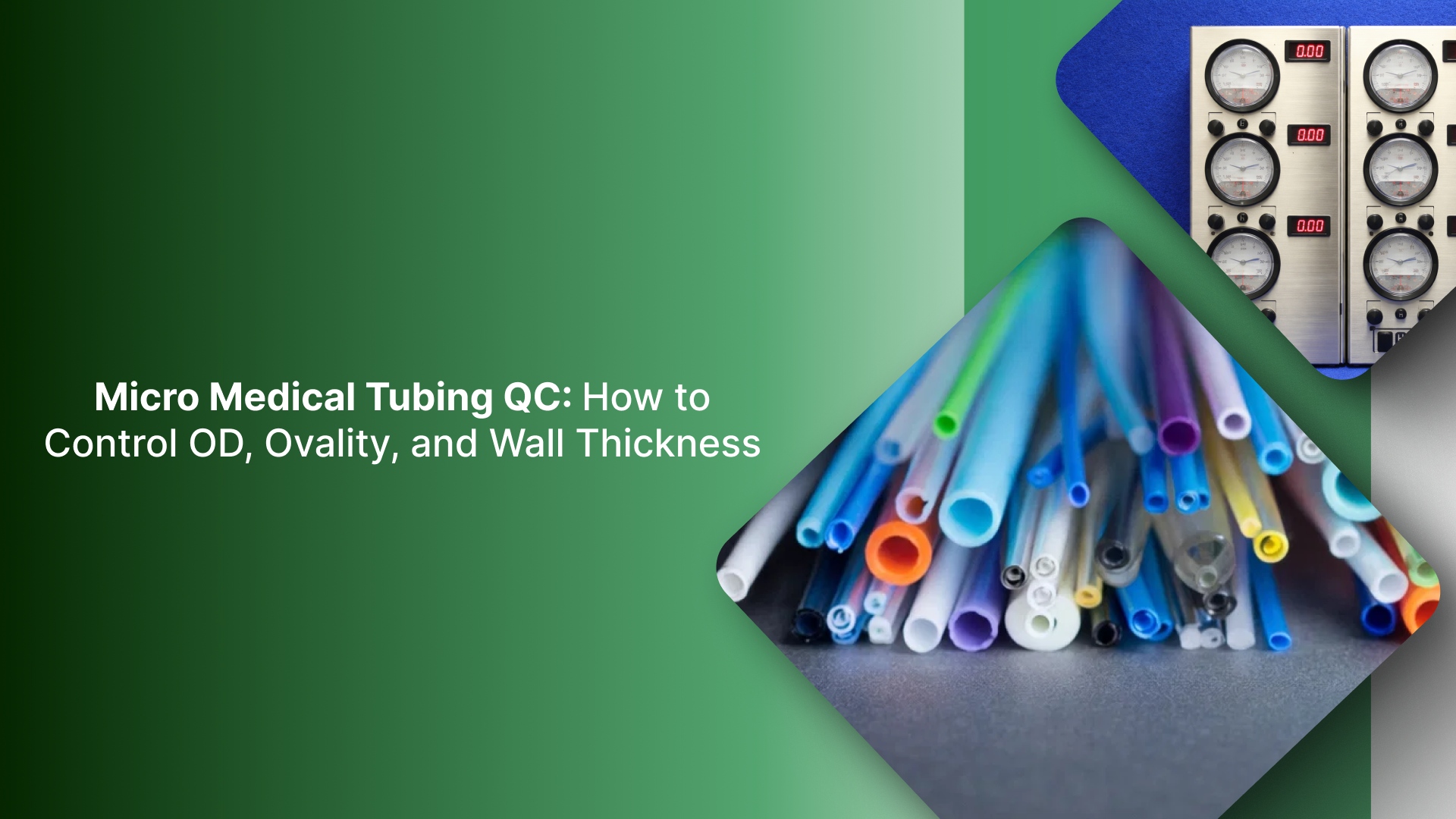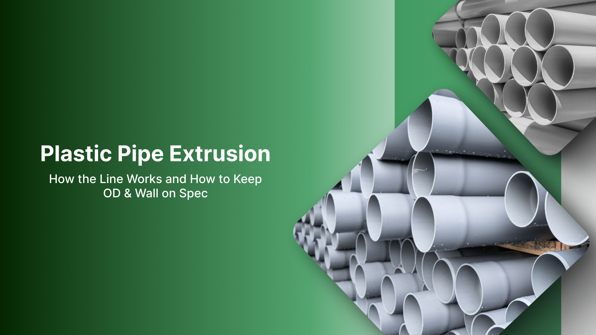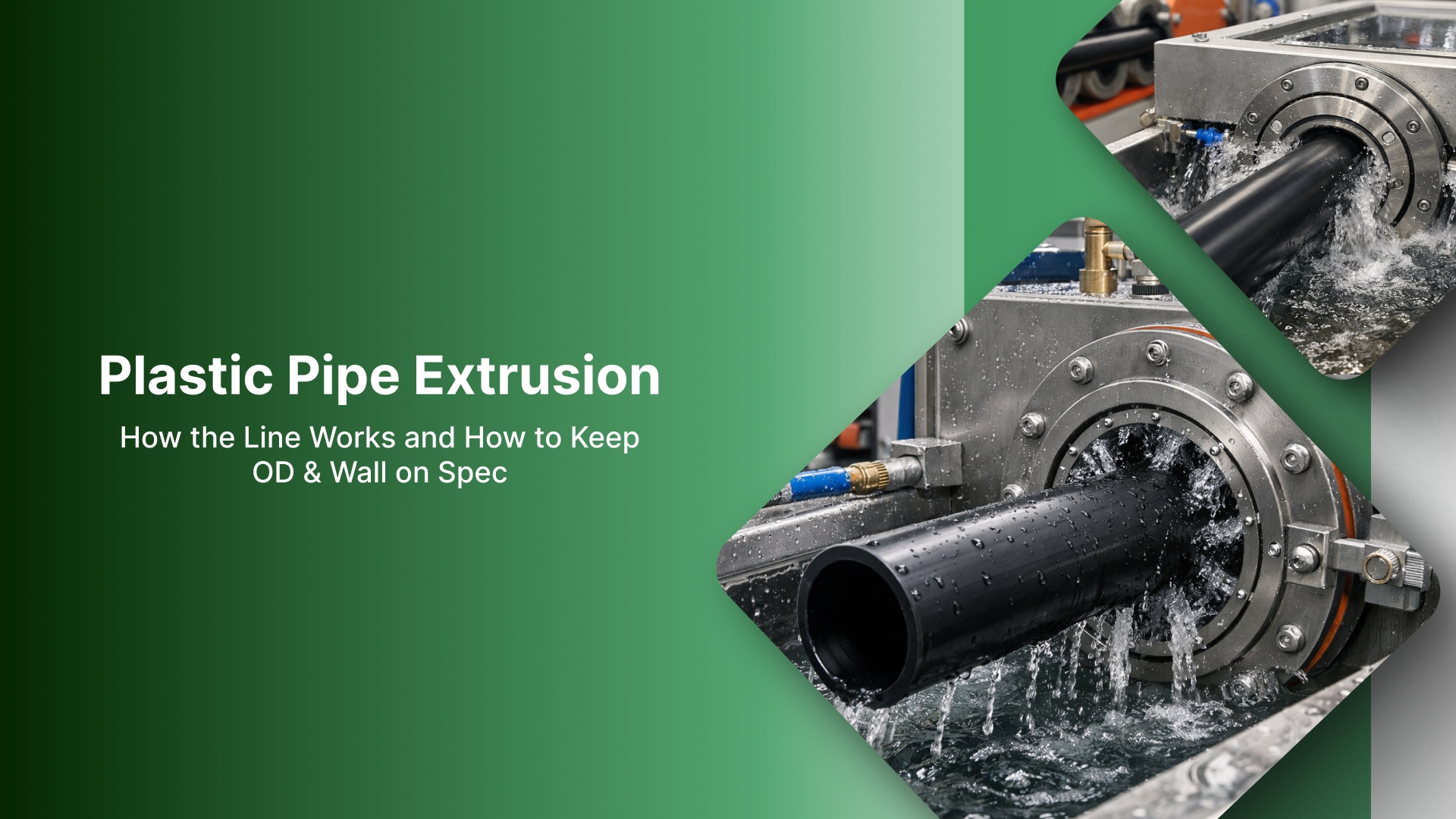
Plastic Pipe Extrusion: How the Line Works and How to Keep OD & Wall on Spec - Google Drive
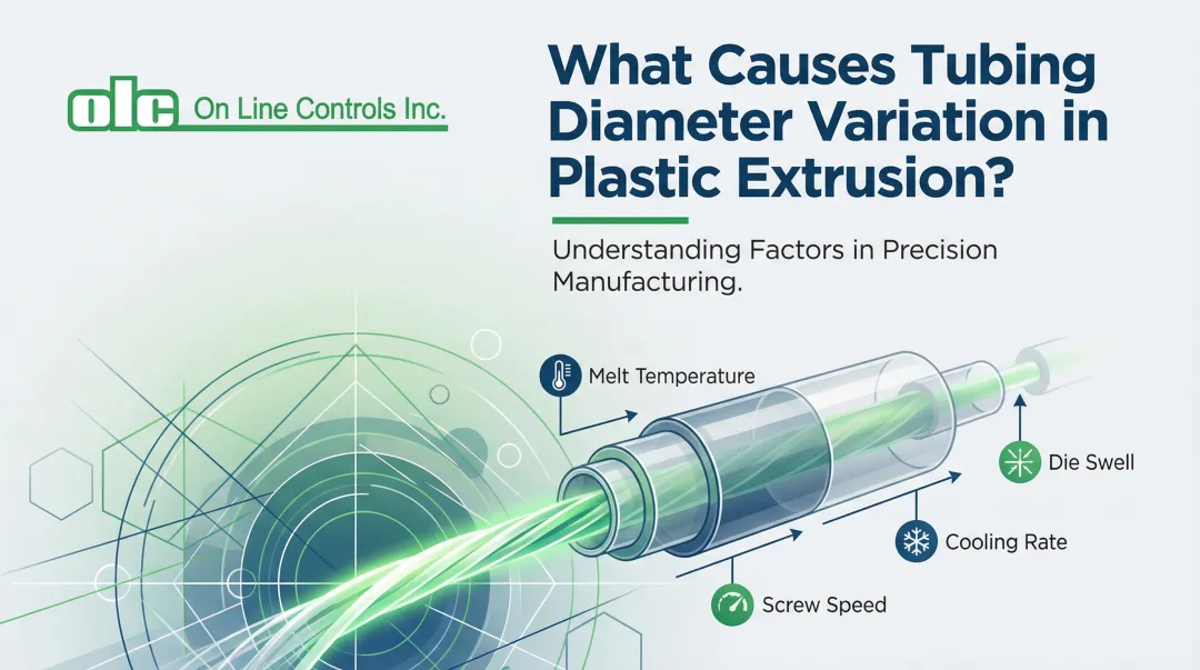
Plastic pipe extrusion appears straightforward at a glance: material is melted, formed through a die, and exits as a continuous pipe or profile. In production, however, dimensional control is the real challenge.
Small shifts in sizing conditions, cooling stability, or line speed can quickly present as OD drift, wall variation, or ovality.
In many extrusion lines, the sizing/calibration stage is where drift is either prevented or amplified. If vacuum and low-pressure support air (used to stabilize the hot pipe during calibration) are not held repeatably, especially when flow demand changes, OD and roundness can drift even when upstream temperatures and haul-off settings appear unchanged.
This guide provides a concise walkthrough of the extrusion line, then focuses on the few variables that most consistently drive pipe size and stability. It also highlights what to check first when output begins to move, so adjustments stay targeted instead of reactive.
Key Takeaways
OD and roundness are most often set in sizing/calibration, not at the die.
The fastest drift checks: support air/vacuum repeatability + sealing, then cooling uniformity, then haul-off stability.
If the line is stable at idle but drifts in production, suspect low-pressure droop/response under demand changes.
How does Plastic Pipe Extrusion Work?
Plastic pipe extrusion melts polymer and pushes the melt through a die to form a continuous pipe. From there, the line stabilizes the hot pipe in sizing/calibration, removes heat in cooling, and uses the haul-off to pull the pipe at a controlled rate.
The output is then cut to length or coiled, depending on the product.
In production, “quality” is primarily dimensional and surface-driven. The core outputs to watch are outside diameter (OD), wall thickness, ovality (out-of-round), and surface finish.
When any of these drift, the cause is usually not the die alone. It typically traces back to stability in the sizing stage (vacuum/support air + sealing + alignment), cooling consistency, haul-off speed/grip behavior, or tooling condition.
The Pipe Extrusion Line: What Each Station Controls
An extrusion line can be viewed as five core stations. Each station influences dimensions differently, so knowing where an issue is introduced makes troubleshooting faster and more targeted.
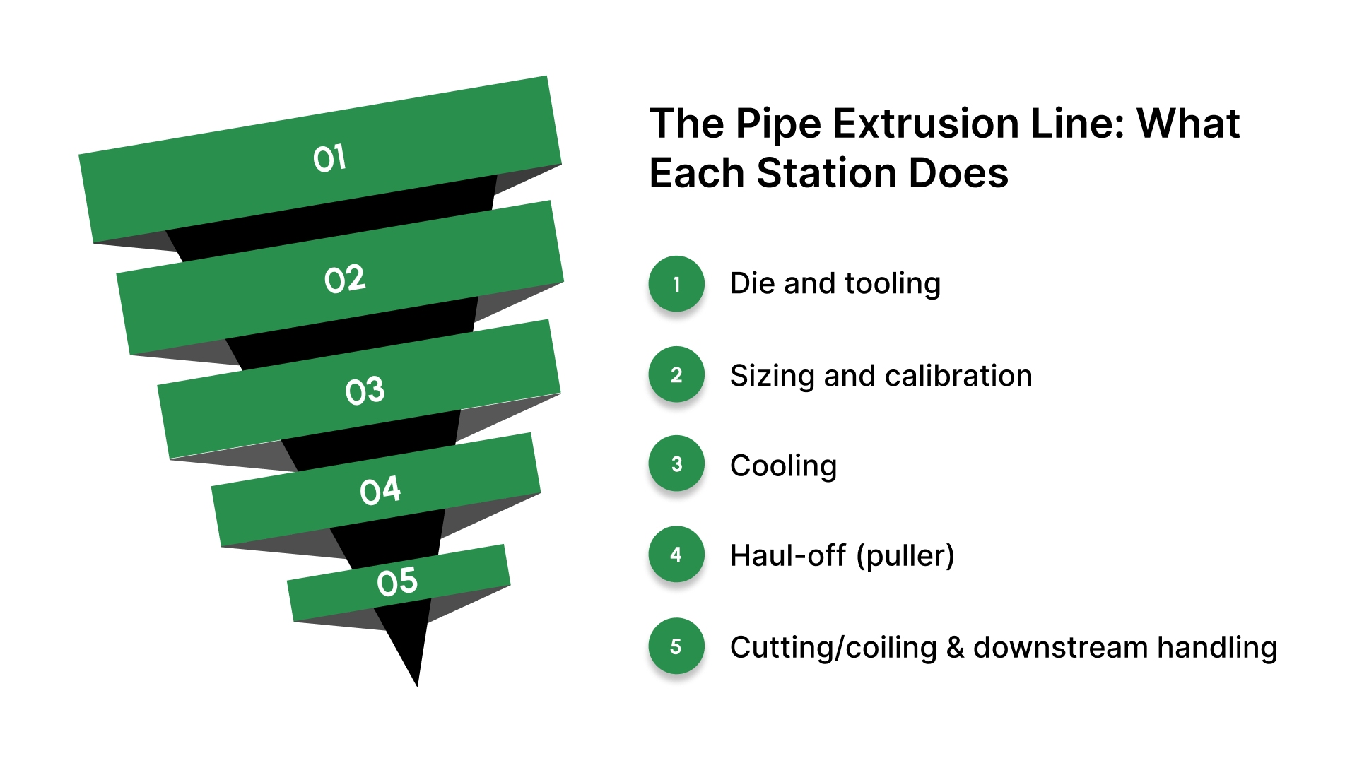
Die and tooling
This is where the melt is formed into the initial pipe geometry. Tooling design, wear, and buildup affect flow balance, which influences dimensions before the pipe reaches sizing.
Sizing and calibration
This stage stabilizes the hot pipe and establishes target OD and roundness. If OD or ovality begins to drift, this is often the first station to verify because the pipe is still soft and being guided into shape.
Cooling
Cooling removes heat, so dimensions “set” and remain stable. Inconsistent temperature, flow, or coverage can cause gradual dimensional movement, ovality changes, and surface variation over time.
Haul-off (puller)
The puller controls line speed and draw. Variations in puller speed, grip, or belt condition can change draw-down behavior, affecting wall thickness and dimensional stability even when upstream conditions appear unchanged.
Cutting/coiling and downstream handling
This stage cuts the product to length or coils it for packaging. It typically does not create true dimensional drift, but it can introduce surface damage, marking, or length inconsistency if handling and support are not controlled.
Once you know which station forms shape, which one stabilizes size, and which one controls draw, it becomes much easier to trace OD, wall, or ovality changes back to the correct adjustment point.
Quick line map: station → what it sets → what drifts → what to check
Use this table as a fast “where do I look?” map when OD, wall, or roundness starts moving during a run.
Line station | What it primarily controls | What you see when it’s off | First thing to check |
|---|---|---|---|
Die / tooling | Initial shape and melt flow balance into the line | Early imbalance, unstable output that sizing cannot fully “correct,” inconsistent finish | Tooling condition, centering/alignment, contamination or wear, temperature consistency |
Sizing/calibration | OD and roundness while the pipe is still soft | OD drift, ovality changes, “won’t hold size” behavior | Support air/vacuum regulation stability (low-pressure repeatability), calibrator condition and alignment, leaks, and sealing surfaces |
Cooling | How quickly do dimensions get locked in | Gradual size movement, ovality changes, and surface issues that come and go | Water temperature stability, flow consistency, tank levels, coverage symmetry |
Haul-off / puller | Line speed and draw through the process | Wall variation, size shifts tied to speed changes, slip marks | Speed stability, belt/track condition, and grip, synchronization with upstream conditions |
Cutter/coiler | Length consistency and downstream handling | Length inconsistency, marking/scuffing, handling defects | Timing/setup, downstream tension/handling, guides, and supports |
The goal is not to adjust everything at once. Identify the station most likely driving the symptom, verify the basics there, then make one controlled change and observe the result.
What actually controls OD, wall, and roundness
If the line stations are the hardware, these are the levers that determine whether OD, wall, and roundness stay stable from minute to minute.
Melt output vs take-off (draw balance)
Pipe dimensions depend on a stable balance between melt output and haul-off draw. When that balance shifts, OD and wall can move even if nothing appears to change visually at the line.
This is why dimensional movement often correlates with speed changes, start-up stabilization, and small output swings.
Support air/vacuum regulation stability (low-pressure repeatability + sealing)
Sizing only works when support conditions are steady. If the vacuum level, support air, or sealing integrity varies, the pipe experiences a different forming force while it is still soft.
The result is gradual OD movement and roundness variation that is difficult to correct with a single downstream adjustment.
Cooling uniformity (temperature + flow + coverage)
Dimensions do not “lock” until cooling is consistent. Uneven or changing cooling conditions can freeze one area faster than another, which introduces slow drift and can bias ovality.
Stable water temperature, stable flow, and consistent coverage matter more than simply increasing cooling.
Tooling geometry and alignment
Small mechanical bias shows up as persistent ovality or wall distribution issues. Wear, buildup, off-center tooling, or uneven support can create repeatable defects that do not respond well to normal tuning.
When these levers remain stable, the line becomes predictable. OD, wall, and roundness hold without constant correction.
Common problems: symptom → first suspect
Use this table to go from what you’re seeing to the most likely first suspect, without changing multiple settings at once.
Symptom pattern | First suspect |
|---|---|
OD drifts slowly over time (no major setting changes) | Support air/vacuum regulation stability (low-pressure repeatability) first, then cooling stability |
OD changes right after a line speed change | Draw balance (melt output vs take-off) |
OD is stable at startup, then wanders after the line “settles.” | Thermal stabilization across sizing/cooling |
Wall varies along the length (thick/thin zones down the run) | Puller speed/grip stability or output consistency |
The wall is uneven around the circumference (one side thicker) | Centering/alignment (die + sizing/calibration) |
Ovality is consistent and repeatable run-to-run | Mechanical geometry (tooling wear, centering, calibration setup) |
Ovality comes and goes during the run | Unstable support air/vacuum conditions or uneven cooling coverage |
Surface marks repeat in the same location | Contact/handling points (guides, puller surfaces, supports) |
Surface finish changes with cooling conditions | Cooling uniformity |
Bubbles/voids are persistent | Material handling/moisture or air entrainment upstream |
Bubbles/voids are intermittent | Intermittent moisture/volatiles, feed inconsistency, or air entrainment upstream (check dryer/venting and hopper feed stability) |
Once you identify the symptom pattern, verify the simplest checks tied to that suspect first. Then make one controlled change and observe the result before moving on.
If your checks are solid but the line behaves differently after a resin change, the material family and grade-to-grade behavior are often the driver.
PVC vs PE/PP: Why the Same Settings Behave Differently
PVC and polyolefins (PE/PP) can run on similar extrusion lines, but they rarely hold dimensions the same way once you tighten tolerances.
The practical difference is how each resin family sheds heat and how quickly the pipe becomes self-supporting during sizing and cooling. That directly changes how sensitive the process is to support air/vacuum stability, cooling symmetry, and draw.
What operators typically notice:
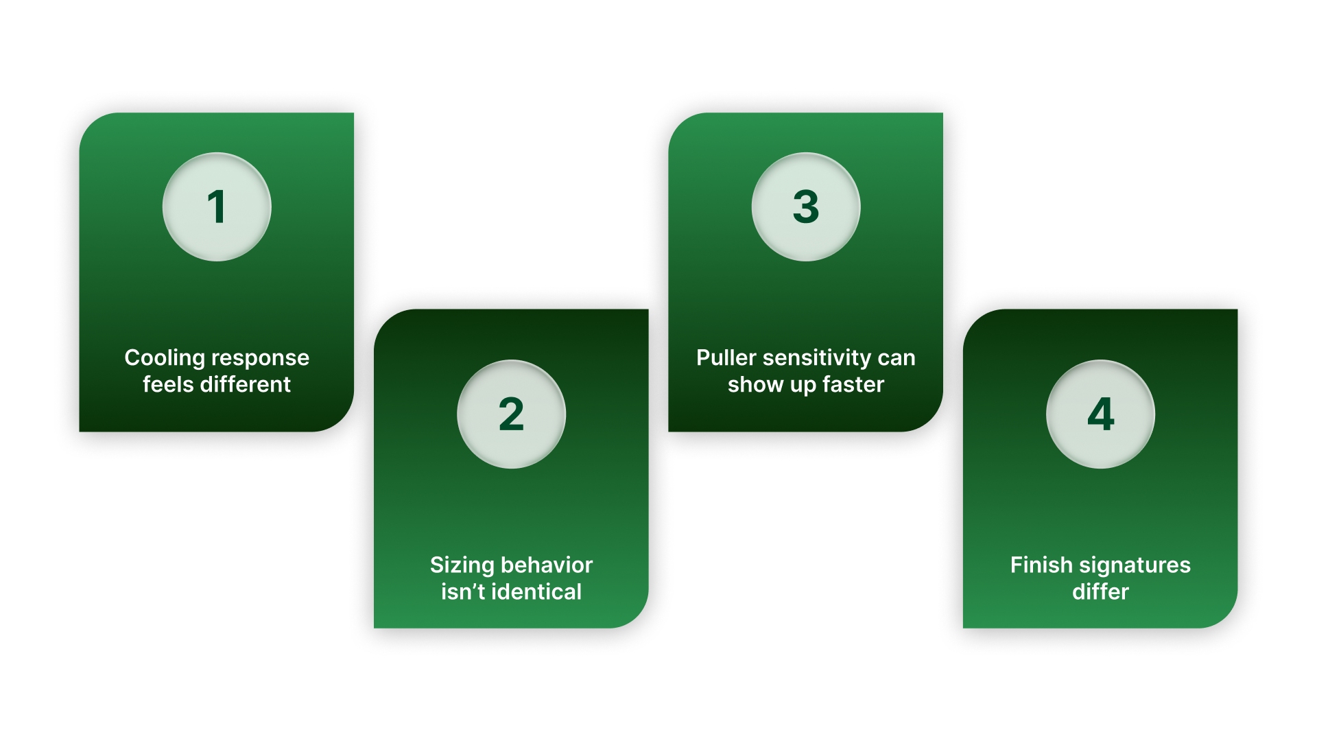
Cooling response is not interchangeable. One material may tolerate small swings in water temperature or flow, while another shows OD/roundness movement or surface changes sooner when cooling conditions drift.
Sizing “takes” differently. Some materials stabilize more easily in calibration. Others are more sensitive to low-pressure support air/vacuum repeatability, sealing integrity, and alignment while the pipe is still soft.
Draw sensitivity shows up faster. The same take-off change can produce different OD/wall response depending on how the melt stretches and freezes, especially during startups and speed transitions.
Surface finish signatures vary. The same handling and cooling setup can create different finish outcomes because each resin freezes differently and reacts differently to contact points.
The resin family and process window change, but the control logic stays the same: keep support air/vacuum regulation stable, keep cooling uniform, and keep draw balanced with melt delivery.
If you’re chasing drift, the quickest gains usually come from improving low-pressure repeatability and stability in sizing/support air before you start chasing temperature and speed setpoints. That’s also where On Line Controls fits.
How On Line Controls Stabilize Sizing and Calibration Conditions
In plastic pipe extrusion, the sizing/calibration stage often determines whether OD and roundness stay stable through normal production shifts. When support air and vacuum conditions vary under real demand, the line can drift even when temperatures and line speed appear steady.
On Line Controls helps extrusion teams stabilize the low-pressure support air/vacuum regulation layer used in sizing/calibration, where small pressure swings at the low end can translate directly into OD drift and ovality.
What On Line Controls supports in practice
Low-pressure regulation for sizing/support air: Helps reduce variation that shows up as OD drift and ovality changes during normal demand shifts.
Repeatable setpoints: Supports consistent settings across operators and changeovers when manual “fine-tuning” creates variation.
Retrofit stability improvements: Targets the control layer first, before you escalate to tooling changes or process rework.
What to specify when selecting low-pressure regulation for sizing/support air
If sizing stability is the constraint, focus on how the regulator performs at low pressure, not just the maximum rating.
Range fit: Select a range where your normal operating point sits in the usable middle of the scale.
Sensitivity: Ensure the adjustment responds in small, predictable increments.
Repeatability: Confirm the regulator returns to the same output after adjustment and over time.
Stability under demand changes (droop behavior): Expect real flow changes. Specify stability when demand shifts, not only at idle.
System discipline (sealing and leaks): Confirm sealing integrity at the calibrator. Regulation cannot compensate for unstable leaks.
If you want to tighten sizing stability, review On Line Controls’ low-pressure regulator options for support air/vacuum service.
Conclusion
Plastic pipe extrusion remains predictable when process control is treated as a stability discipline. Use the station map to identify where variation is being introduced, then correct one variable at a time instead of making broad adjustments across the line.
In practice, the most reliable path to holding OD, wall, and roundness is to keep the draw balanced, maintain repeatable sizing support conditions (support air/vacuum + sealing), and ensure cooling coverage and alignment remain consistent over time.
When those fundamentals are stable, dimensional drift becomes easier to prevent and faster to correct.
FAQs
What is plastic pipe extrusion?
Plastic pipe extrusion is a continuous process where polymer is melted and pushed through a die to form pipe, then sized and cooled to lock OD, wall, and roundness before downstream cutting or coiling.
What equipment is used in a pipe extrusion line?
Most lines include an extruder, die/tooling, sizing/calibration equipment (vacuum tank and/or support air), cooling tanks, a haul-off/puller, and a cutter or coiler, plus measurement and handling equipment as required by tolerance targets.
How do you control OD and roundness during pipe extrusion?
OD and roundness are most directly influenced by stable sizing/calibration conditions. Start by verifying support air/vacuum repeatability, sealing integrity, and calibrator alignment. Then confirm cooling uniformity and haul-off stability.
What causes wall thickness variation in extruded pipe?
Wall variation is commonly driven by changes in draw balance (melt output vs puller speed/tension), puller grip variation, or alignment issues that bias flow and support. The pattern matters: lengthwise variation often points to speed/output stability, while circumferential bias often points to centering/alignment.
What is vacuum sizing (calibration) in pipe extrusion?
Vacuum sizing (calibration) is the stage where the hot pipe is stabilized to its target OD and roundness while still soft. Vacuum and sealing help hold the pipe to the calibrator surface, and support air may be used to maintain internal geometry depending on the setup.