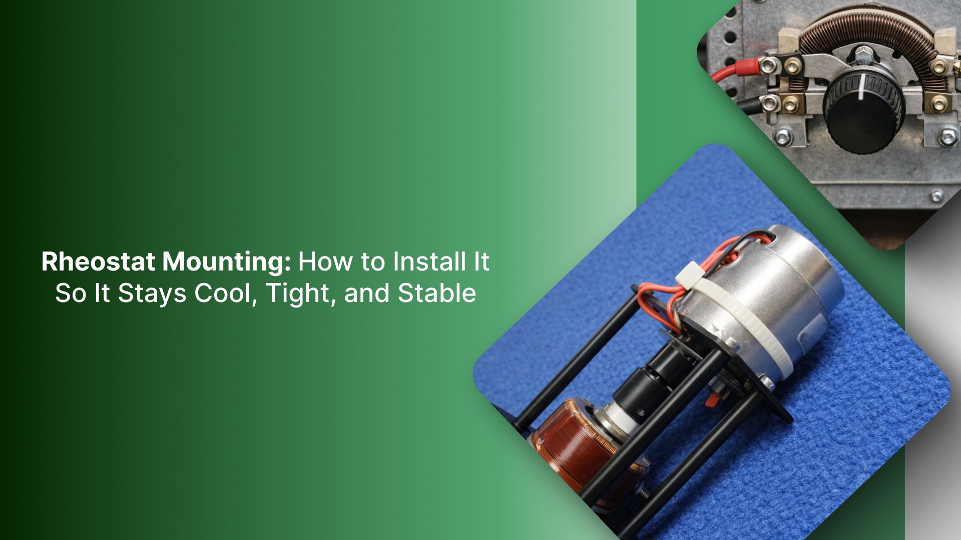
Rheostat mounting looks like a hardware detail. In the field, it decides whether the fix lasts.
A rheostat is a resistor that’s meant to dissipate power as heat. If it’s mounted wrong, you get predictable failures: drift, intermittent wiper contact, cooked insulation, loose terminals, or a panel hot spot that takes out the next component.
This guide is built for real retrofits and replacements. You’ll learn how to identify what you’re actually mounting, choose the right mount style for the enclosure, and install it so it survives vibration, heat, and operator use.
You’ll also get a short verification checklist to run before closing the panel and signing off.
Key Takeaways
Mount a rheostat based on heat, access, and mechanical support, not just “it fits the hole.”
Confirm shaft + bushing fit (panel thickness, thread engagement, knob clearance).
Keep heat sources away from wiring and sensitive components (leave airflow and spacing).
Use proper strain relief so vibration and handling do not stress terminals/leads.
Verify operation under real conditions: smooth resistance change, stable output, and no overheating under load before considering the job complete.
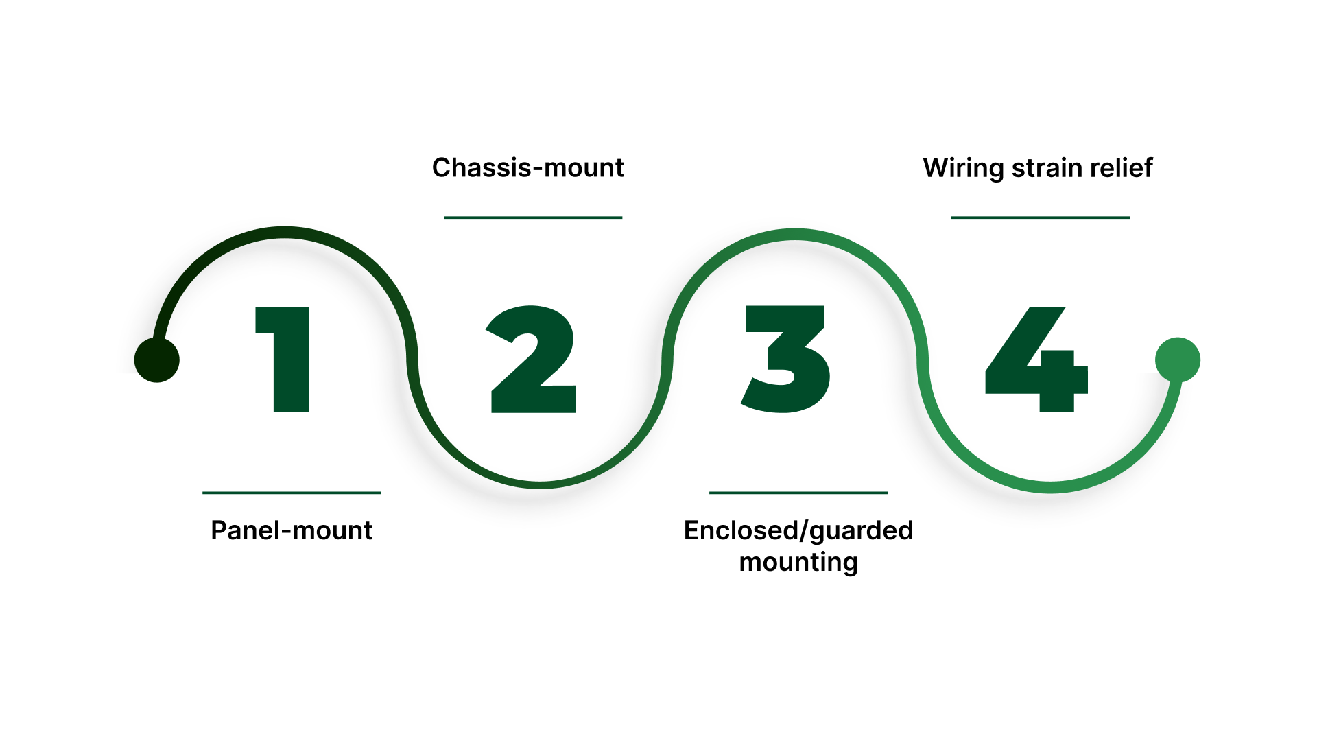
Pick the right mounting style for the job
Before you measure holes or order hardware, decide how the rheostat will be mounted. Mounting style determines three things that drive real-world reliability: how the heat leaves the part, how well the body is supported, and how safely the adjustment can be accessed.
Rheostat mounting styles: Quick decision table
Decision factor | Panel-mount (shaft/bushing through panel) | Chassis-mount (base mounted to metal surface) | Enclosed/guarded (protected housing) |
|---|---|---|---|
Best for | Operator-adjusted knob, retrofits, light–moderate dissipation | Higher dissipation, rugged installs, vibration-prone setups | Exposed areas, safety-driven installs, harsh environments |
Heat handling | Limited; depends on body size + airflow behind panel | Better, a mounting surface can act as a heat sink | Varies; enclosure design and ventilation decide |
Access & adjustment | Best (front-of-panel adjustment) | Varies; often not intended for frequent adjustments | Controlled; adjustment protected/limited |
Mechanical support | Moderate; panel supports body (needs anti-rotation) | High; base mounting supports body and wiring | High housing adds protection and support |
Environment protection | Low unless inside an enclosure | Moderate; depends on enclosure | High: guards against debris and accidental contact |
Primary watch-outs | Heat buildup behind panel; shaft/bushing mismatch; loosening/rotation | Needs a solid mounting surface, clearance, and airflow; keep heat away from wiring | Enclosure can trap heat; ensure access and ventilation are adequate |
How to choose the mounting style fast
If the rheostat will dissipate significant heat continuously, lean chassis-mount or guarded/enclosed with proven ventilation.
If operators must adjust it regularly from the front panel, choose panel-mount, but treat heat and anti-rotation as design requirements.
If vibration or cable pull is common, chassis-mount usually survives better than a “hanging behind the panel” install.
If the unit is exposed to bumps, debris, or accidental contact, guarded/enclosed is the safer choice.
After you choose the mounting style, confirm the key dimensions first, cause most install rework starts with a fit mismatch.
Rheostat mounting fit checklist
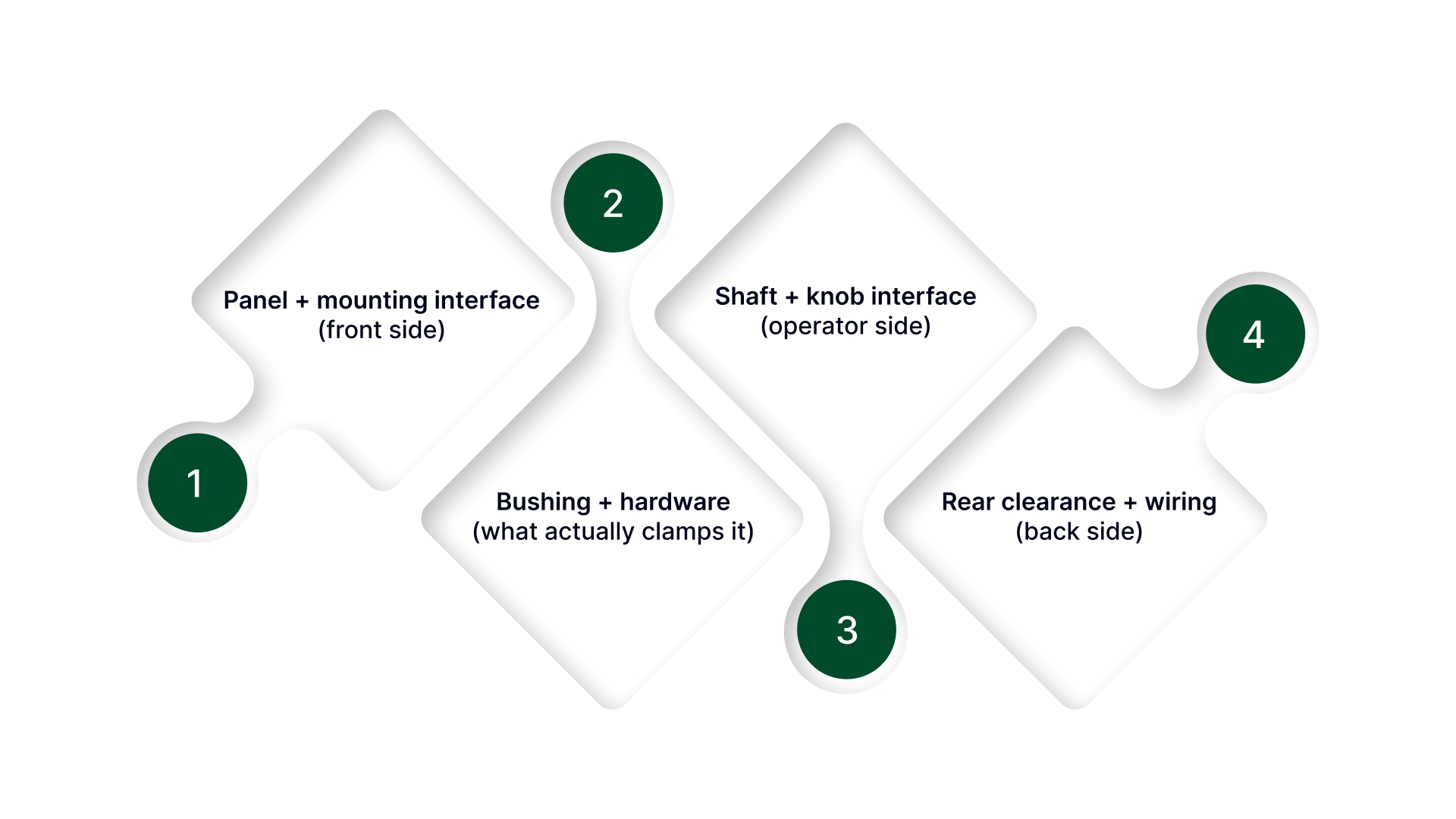
Matching ohms and watts is not enough. This checklist covers the measurements that determine whether the rheostat actually fits the panel and enclosure.
Panel + mounting interface (front side)
Panel thickness
Measure actual sheet/door thickness (include paint/powder coat if it matters).
Confirm the mounting style you chose supports that thickness.
Mounting hole/cutout
Measure the hole diameter (or cutout dimensions if it’s not round).
Check for anti-rotation features (tab, flat, keyed washer, D-hole).
If the panel has an anti-rotation tab slot, confirm the new rheostat hardware matches it.
Bushing + hardware (what actually clamps it)
Bushing thread size and pitch: Match the exact thread spec (don’t assume “it’s close enough”).
Usable thread engagement:
Confirm there’s enough thread to fully clamp the panel with any washers, lock washers, and nameplates in place.
If thread engagement is marginal, you’ll get loosening and intermittent contact over time.
Shaft + knob interface (operator side)
Shaft diameter: Confirm the shaft diameter matches your knob/coupler (¼”, 6 mm, etc.).
Shaft length above the panel: Measure the required stick-out for the knob to seat correctly (including skirt clearance if used).
Shaft style:
Identify the interface: round, D-flat, keyed, splined.
Confirm how the knob locks: set screw, collet, push-on.
If you mismatch this, the knob will slip or won’t mount at all.
Rear clearance + wiring (back side)
Rear depth clearance: Measure clearance from the panel to the nearest obstruction (ducting, DIN rail, covers, door swing hardware).
Terminal clearance + bend radius
Make sure there’s room for terminals and a safe wiring bend radius (especially with ring/fork lugs).
Plan for service access: terminals you can’t reach become a future downtime problem.
Terminal type + orientation
Identify terminal style: screw terminals, solder lugs, quick-connect tabs, studs.
Confirm orientation so terminals/lugs don’t collide with covers or force the wiring into a tight bend.
With the fit confirmed, the next step is mounting it so it stays tight, runs safely, and can be serviced without tearing the panel apart.
Mounting steps by style (panel, chassis, enclosed)
Even with the correct mounting style and the right electrical ratings, rheostats often fail early due to mechanical stress at the terminals or poor physical support.
The goal of mounting is not just “secure it to the panel.” It is to prevent rotation, protect the terminals from being used as a load-bearing point, and route wiring so vibration and door movement cannot loosen lugs or create shorts.
The steps below break the install down by mounting style, with strain relief treated as a required part of the mounting job, not an optional finishing touch.
Panel-mount
Prep the panel hole: Confirm hole size, panel thickness, and any anti-rotation feature (flat, tab slot, keyway) are correct and burr-free.
Build the washer stack: Use the manufacturer’s recommended flat washer + lock washer arrangement. Add a jam nut if vibration is expected or if the knob will see frequent adjustment.
Seat the anti-rotation feature: Engage the tab/flat/key so the body cannot rotate when the knob is turned.
Tighten the bushing nut correctly: Hold the body steady and tighten from the front. Do not use the terminals as a “handle.”
Route wiring with clearance: Ensure terminals have room for lug width and bend radius without contacting the panel, door, ducting, or covers.
Chassis-mount
Mount to a rigid surface: Use a solid baseplate or chassis surface that can support weight and vibration without flexing.
Maintain service clearance: Leave room for tool access, terminal maintenance, and replacement without removing unrelated hardware.
Orient for airflow and wiring: Position the unit so terminals are protected and wiring does not cross hot surfaces. If convection cooling matters, avoid trapping it behind barriers.
Secure the body, not the terminals: Mounting force should be carried by the bracket/base, not by the wiring or lugs.
Enclosed/guarded mounting
Bond/ground where applicable: If the enclosure or device design calls for bonding, ensure proper grounding of metallic housings and door hardware.
Route wiring with protection: Use grommets, edge protection, and internal ducting so conductors do not rub on sheet metal or hinge paths.
Preserve adjustment access: Ensure the adjustment method (knob/shaft/coupling) is reachable without forcing awkward angles that encourage overtightening or side-loading.
Wiring strain relief
Use insulation boots or covers on terminals, especially in tight enclosures where a door closure could shift wiring into contact.
Keep wiring off sharp edges and heat sources: Add grommets/edge trim, and maintain separation from resistive bodies and hot chassis areas.
Tie down the harness: Add a tie point close enough that the wire cannot transmit pull force to the terminal during vibration or panel-door movement.
Design for door movement: If the rheostat is on a door, route with a service loop and fixed anchors so opening/closing does not flex lugs or loosen connections.
Prevent lug rotation: If movement could twist a lug into a short, adjust terminal orientation (or use angled lugs) and secure the harness to hold its geometry.
With the hardware mounted and wiring protected, the next constraint is thermal, because even a perfect mechanical install fails early if the rheostat is forced to dissipate heat with no margin.
Wattage and heat management for rheostat mounting
A rheostat turns electrical power into heat on purpose. If the mounting location traps that heat, the result is predictable: drift, noise, cooked insulation, or a failed wiper/element. Treat mounting as a thermal decision, not a cosmetic one.
Placement rules so heat can leave the part
Avoid dead-air pockets.
Do not mount directly above transformers, VFDs, contactors, or heaters where hot air rises and accumulates.
Keep it away from heat-sensitive wiring and plastics.
Route harnesses so they do not pass over the rheostat body. Maintain separation from cable ducts and wire bundles.
Mount to something that can reject heat when dissipation is meaningful.
If the rheostat is expected to run warm, chassis/metal backing helps. Thin panel-only mounting can trap heat behind the panel.
Leave service/inspection clearance.
If you cannot visually inspect terminals and insulation after a run, you will miss early signs of overheating.
Plan airflow direction, not just “space.”
If the enclosure has forced ventilation, orient the rheostat so airflow crosses the body, not just the shaft area.
Duty cycle changes what “enough wattage” means
Set up/trim use: short adjustments with low average dissipation.
Heat spikes may be acceptable if the part cools between uses.
Continuous load control: steady dissipation for long periods.
This is where marginal mounting fails. If the process expects the rheostat to be warm or hot all day, the installation needs a real thermal margin (and often a different control approach).
Practical rule: If it must run hot continuously to do its job, you’re operating near the edge. Either step up in wattage and heat sinking, or move to a control method that does not waste power as heat.
Simple field check
Run the system at typical operating conditions and check:
Heat rise trend: temperature should stabilize, not climb indefinitely.
Odor and discoloration: hot phenolic smell, darkening, or brittle insulation indicate excessive temperature.
Setting stability: if the output drifts as it warms, you are seeing thermal effects or contact stress.
Nearby wiring condition: insulation should not soften, gloss, or deform near terminals.
If any of these appear, treat it as a thermal issue first, not a “bad rheostat.”
When to change the approach
You should reconsider the setup when:
The rheostat cannot be touched safely during normal operation.
The enclosure temperature climbs noticeably after installation.
You are repeatedly replacing units despite correct wiring.
The process requires continuous dissipation near the device limit.
In those cases, the fix is typically one of the following:
Increase wattage and improve heat rejection (chassis mount, better airflow, more spacing).
Reduce the dissipated power by changing the circuit approach.
Use a controller-based method when the application is really asking for repeatable speed/power control rather than resistive limiting.
If heat is controlled but the setting still wanders or jumps over time, the next culprit is usually mechanical loosening or wiper behavior under vibration.
So the next step is locking the adjustment and stabilizing the mechanics.
Prevent drift and plan failure behavior
A rheostat can be mounted correctly and still cause problems if the setting drifts in vibration or if the wiper contact becomes intermittent.
This section focuses on the two stability risks that show up after commissioning: mechanical movement over time and wiper behavior under real operating conditions.
Keep the setting from drifting (mechanical stability)
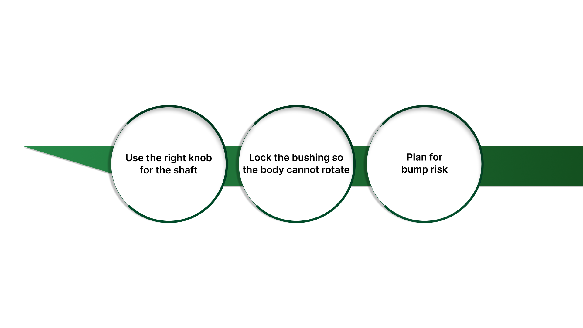
Use the right knob for the shaft
Match the shaft type (round, D-flat, keyed) to the knob bore.
Prefer a set-screw knob on a D-flat or keyed shaft so the knob cannot “walk” under vibration.
Avoid friction-fit knobs in panels that see door slams, vibration, or operator bumping.
Lock the bushing so the body cannot rotate
Use a jam nut (or lock washer + proper torque) so the rheostat does not loosen over time.
If the unit has an anti-rotation tab/key, use it. If the panel cutout supports it, this prevents twisting that can stress terminals.
Plan for bump risk
If operators can hit the knob, add a guard, recessed mounting, or a locking knob style.
If the setting is critical, add a mechanical stop or reference marks so drift is visible.
Recognize wiper problems early (electrical stability)
Intermittent wiper contact is one of the most common “it was fine, then it wasn’t” failures.
Watch for these field symptoms:
Sudden jumps in output when the knob is barely moved
Dead spots where rotation produces little or no change, then resumes
Noisy or unstable output that changes with vibration or temperature
Output that intermittently rails (goes near the minimum or maximum unexpectedly)
If you see these, treat them as a reliability issue, not a tuning issue. The correct action is usually replacement with an appropriate construction rating (and confirming the circuit’s preferred fail mode).
What happens if the wiper opens
A key safety/reliability question is: If the wiper loses contact, what does the circuit do?
In many setups, an open wiper can make the circuit behave like:
Maximum resistance (often “fails low” current)
Minimum resistance (often “fails high” current)
Or it can jump unpredictably if the wiring is marginal
Fail-direction thinking (simple rule):
Prefer fail-low where an unexpected high output would create risk (speed, heat, tension, flow).
Prefer fail-high only when loss of output creates the greater risk (application-specific, but less common).
This is not just an electrical decision. It is a process risk decision. If the consequence of a wiper event is unacceptable, do not rely on a marginal contact element or mounting scheme.
Once drift control and failure behavior are defined, the final step is to verify performance under real load conditions before the installation is considered complete.
Go/no-go verification checklist
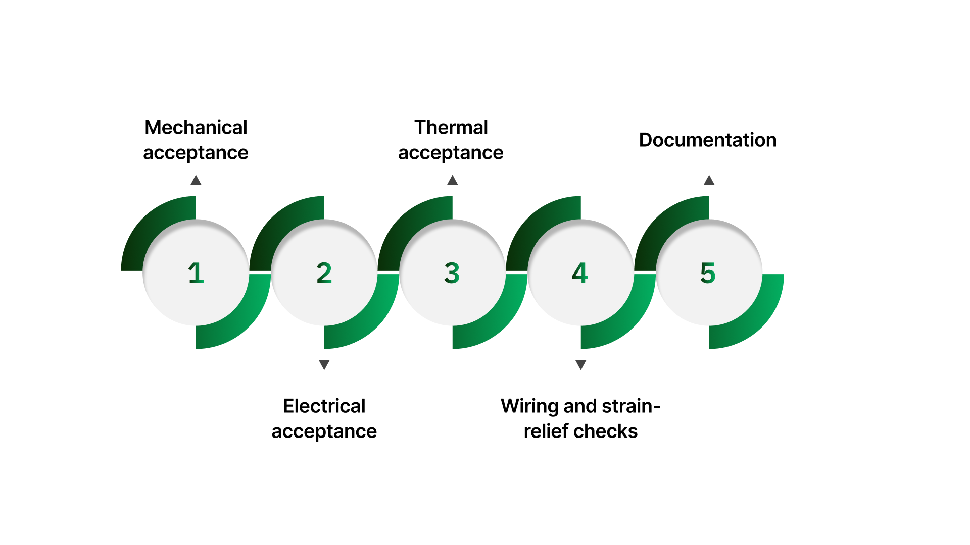
Before you close the panel and return the machine to production, you want one thing: proof that the rheostat is mechanically secure, electrically stable, and thermally within margin under real operating load.
This checklist is an acceptance gate, not a troubleshooting guide.
Mechanical acceptance
Full travel clearance
Knob/shaft turns end-to-end without scraping the panel, guard, or enclosure.
No interference with adjacent hardware, door swings, or cable duct covers.
No body rotation
The rheostat body does not twist when the knob is turned.
Anti-rotation feature (tab/key) is engaged if present.
Hardware stays tight after cycling
After a short run and several knob cycles, re-check the bushing nut/jam nut for loosening.
No visible movement at the bushing, bracket, or chassis mounts.
Electrical acceptance
Smooth response
Adjustment produces a consistent, predictable change (no “all the change at one end” surprises unless expected by design).
Output does not “hunt” when left in a fixed position.
No dropouts or jumps
No sudden steps, dead spots, or intermittent open behavior during slow sweep.
No noise bursts correlated with vibration, door movement, or cable movement.
Stable at steady state: At the intended setting, the system holds the expected operating condition without drift that forces re-tuning.
Thermal acceptance
Temperature rise at normal duty
Run the process at a typical load and duty cycle long enough to reach steady behavior.
Confirm it does not produce excessive heat for the enclosure (hot wiring nearby, odor, discoloration, or rapid drift are immediate red flags).
Heat is not stressing adjacent components: No heating of nearby harnesses, terminals, ducting, or plastic parts due to proximity.
Wiring and strain-relief checks
Strain relief holds
Tug test: cable movement does not transfer force into terminals or lugs.
The door opening/closing does not pull or flex the rheostat connections.
Terminals don’t move
No terminal twisting during operation or adjustment.
Boots/insulation remain seated; no contact risk against chassis or other conductors.
Documentation
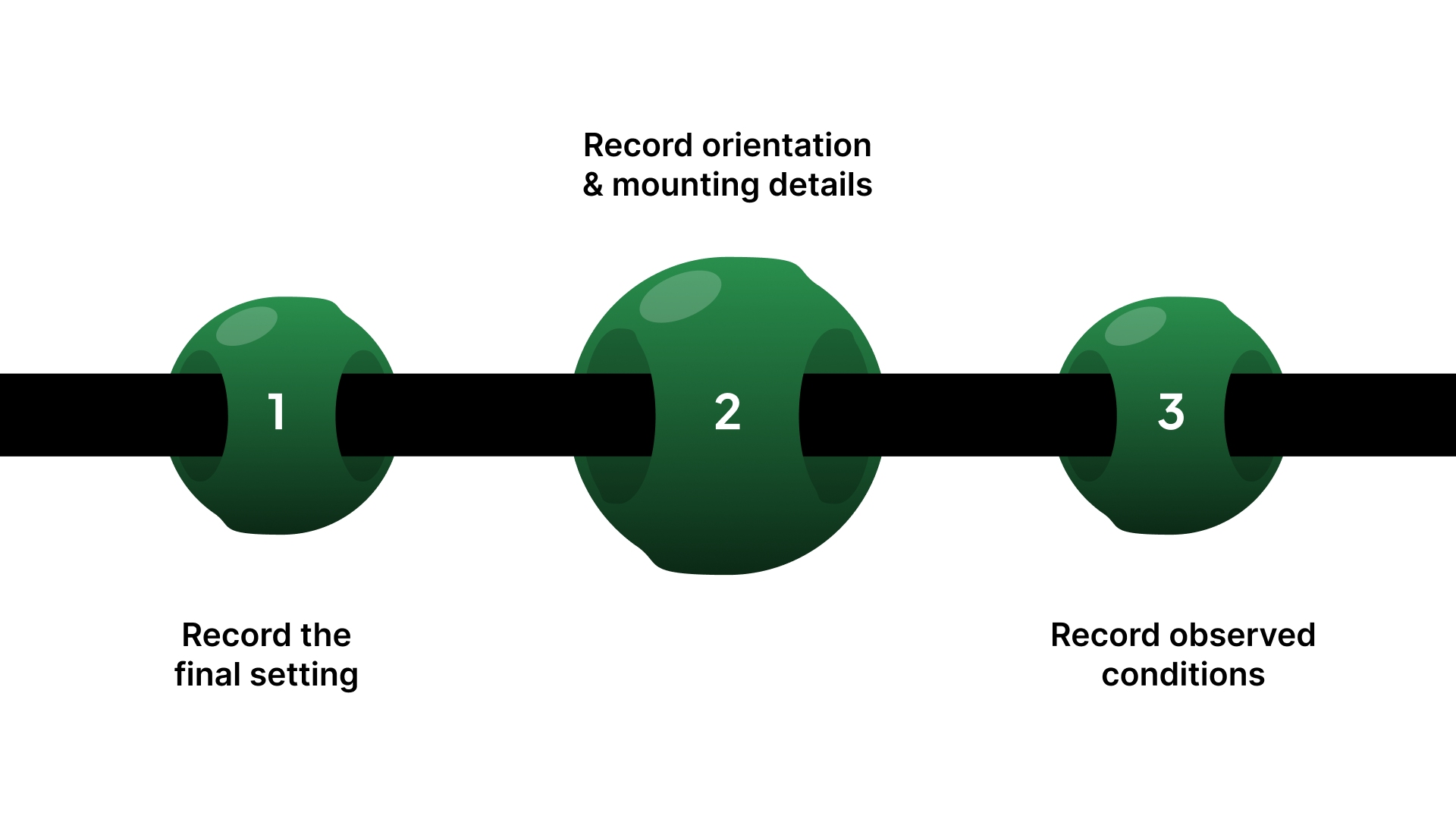
Record the final setting: Knob position reference (marking, scale, or photo), and direction convention (CW increases/decreases).
Record orientation and mounting details: Mount style, location, and any guards/locking method used.
Record observed conditions: Duty cycle during check, approximate enclosure temperature, and whether it was verified at production load.
If your go/no-go checklist is pointing to repeated overheating, loose settings, or “it works on the bench but not in the panel,” the next step is usually a spec confirmation.
How On Line Controls helps prevent repeat rheostat failures
Repeat failures tend to come from the same three gaps: wrong mechanical package, not enough thermal margin, or an unstable setting under vibration.
Mechanical fit that doesn’t turn into rework: Correct bushing/shaft hardware, terminal orientation, and clearance so the unit mounts cleanly and the door closes without stressing lugs.
Predictable heat: Align wattage and mounting style to real duty cycle and enclosure conditions so the rheostat isn’t forced to run at the edge.
A setting that holds: Options and setup practices that reduce loosening, knob creep, and “touch it every shift” behavior.
When the knob shouldn’t be manual anymore: Motorized adjustment options when access, repeatability, or safety is the real constraint.
You’re not relying on generic catalog matching here. The value is in matching the mount + load + enclosure reality and knowing when the symptom is wear (wiper/track) versus installation stress or heat.
If you want a quick spec-and-install sanity check before you close the panel, send a front + rear photo and these five details:
Ohms + watt rating (photo of label is fine)
Mounting style (panel/chassis / enclosed) + where it sits in the enclosure
Load and duty cycle (setup trim vs continuous under load)
Any symptoms you’ve seen (hot smell, drift, dead spot, intermittent jump)
Enclosure conditions (ambient temp/airflow / nearby heat sources)
We’ll flag the common risk points (heat, fit, terminal stress, drift) and suggest what to change before it turns into a repeat failure.
Conclusion
Rheostat mounting is not a cosmetic choice.
It determines whether the part can dissipate heat safely, stay mechanically secure, and remain serviceable over time.
The most common failures happen when the mechanical package is treated as an afterthought, incorrect ohms and wattage, or the wrong mounting style, poor clearance, stressed terminals, or a heat-trapped enclosure.
The reliable approach is simple: choose the mounting style based on heat and access, measure the panel and shaft interface before ordering, install with proper locking and strain relief, then verify smooth operation under real load conditions.
If the unit runs hot, the setting drifts, or failures repeat, treat it as a specification and installation match problem, not a trial-and-error replacement cycle.
FAQs
How do you mount a rheostat in a control panel?
Use a panel-mount rheostat with the threaded bushing through the panel cutout, then secure it with the correct nut + lock washer stack. Make sure the body/terminals have rear clearance, and that wiring is strain-relieved so the terminals don’t carry mechanical load.
What’s the difference between a panel-mount and a chassis-mount rheostat?
Panel-mount is designed for front access and light mechanical support through the bushing/nut. Chassis-mount is meant to be bolted to a rigid surface for better support and heat handling when dissipation is higher (and the knob/shaft can be extended or guarded as needed).
What size hole and panel thickness can a panel-mount rheostat handle?
The hole/cutout size and maximum panel thickness are model-specific—use the datasheet for the bushing thread and the allowable panel thickness. Even accessory hardware (like mounting/coupling kits) is specified by model and max panel thickness, so don’t guess.
Can a rheostat be mounted in any orientation (vertical/sideways)?
Often, yes, mechanically, but orientation changes heat behavior and how debris can settle on/around the element. Treat it as a thermal + contamination decision: maintain airflow, avoid dead-air pockets, and keep the hot body away from wiring, ducting, and surfaces operators might contact.
Why does a rheostat “work on the bench” but fail after mounting in the panel?
In the panel, you usually add heat soak, restricted airflow, vibration, and terminal stress from stiff wiring. Those four factors drive early drift, intermittent contact, and cooked insulation—so verification under real load and with the door closed is the real acceptance test.