Introduction
Picture a hydropower operator adjusting a wicket gate while watching analog gauges respond instantly—voltage needles sweeping smoothly across dials as water flow changes and power output climbs. This is analog feedback in action: continuous electrical signals representing physical conditions in real-time, automatically adjusting system parameters without the delays of digital computation.
Analog feedback uses continuous voltage, current, or resistance changes—not discrete digital samples—to monitor and control hydropower systems. A potentiometer on a gate linkage produces a smoothly varying voltage as the gate opens; a tachometer generates an analog signal that rises and falls with turbine speed.
These signals feed directly into controllers that respond in milliseconds, enabling precise real-time adjustments.
This immediate responsiveness explains why analog feedback remains the backbone of hydropower control, even as digital systems run modern control rooms. Over 50% of global hydropower capacity exceeds 30 years old, and many facilities still rely on proven 4-20mA current loops and 0-10V signals for critical control.
Operators trust analog systems because they're simple, reliable, and fail in predictable ways—qualities essential when managing infrastructure that must respond instantly to grid demands.
Key Takeaways
- Analog feedback continuously monitors turbine gates, generator voltage, and shaft speed in real-time
- Powers wicket gate positioning, turbine speed governing, and automatic voltage regulation
- Analog persists because it eliminates computation delays, requires no sampling intervals, and provides inherent fail-safe behavior
- Core components: position sensors (LVDTs, potentiometers), PID controllers, and actuators (servomotors, governors)
- Hybrid systems overlay digital SCADA on analog loops for data analytics while maintaining fast response
What Is Analog Feedback in Hydropower Control?
Analog feedback is a control method where continuous electrical signals represent physical parameters—gate position, turbine speed, generator voltage—and are fed back to controllers to maintain desired setpoints.
Unlike digital systems that sample data at intervals, analog signals change smoothly and continuously, mirroring the physical world without discrete steps.
Analog vs. Digital: A Fundamental Difference
Consider a wicket gate moving from 30% to 50% open. A potentiometer provides a voltage that rises smoothly from 3V to 5V as the gate travels—an infinite number of values across the range. A digital encoder, by contrast, outputs discrete steps: 30.0%, 30.1%, 30.2%, and so on. Analog signals are continuous. Digital signals are sampled.
Why does this matter? Turbines respond to rapid changes in water flow and electrical load. Analog feedback provides instantaneous correction without waiting for the next sample interval or computation cycle.
Key differences:
- Analog: Infinite resolution, continuous measurement, instant response
- Digital: Discrete steps, sampled intervals, computation delays
- Analog: No conversion lag between physical change and signal
- Digital: Requires analog-to-digital conversion time
Standard Signal Types
Hydropower plants use three primary analog signal types:
- 4-20mA current loops - Industry standard for long cable runs; the signal is immune to voltage drops and electrical noise. The 4mA "live zero" allows controllers to detect broken wires (0mA = fault)
- 0-10V voltage signals - Common for short-distance cabinet wiring and position sensing; simpler interface but susceptible to noise over distance
- Resistance changes - Direct potentiometer feedback where resistance varies with position; often converted to current or voltage for transmission
According to research on hydropower fleet demographics, approximately 50% of global hydropower capacity is older than 30 years, with a significant portion still relying primarily on analog control systems. Digital governors face obsolescence cycles of 5-15 years, while analog and mechanical components can often be refurbished indefinitely.
Hybrid Approaches
Modern plants increasingly adopt hybrid architectures: analog feedback handles critical real-time control (wicket gates, speed governing), while digital systems provide monitoring, data logging, and remote operation. The hybrid approach preserves the proven reliability and millisecond response of analog loops while gaining the diagnostic capabilities of digital SCADA.
How Analog Feedback Works in Hydropower Systems
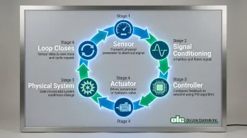
Analog feedback operates through closed-loop control: a sensor measures a physical parameter, converts it to an electrical signal, a controller compares this signal to a setpoint, and an actuator adjusts the system to minimize error. The process repeats continuously, creating a self-correcting loop.
The control sequence:
- Sensor - Converts physical position, speed, or voltage to electrical signal
- Signal conditioning - Amplifies, filters, and isolates the signal
- Controller - Compares feedback to setpoint using PID algorithms
- Actuator - Drives servomotor or hydraulic valve to correct error
- Physical system - Gate moves, turbine speeds up/down, voltage changes
- Loop closes - Sensor detects new state and cycle repeats
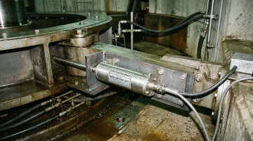
Wicket Gate Position Control
Wicket gates regulate water flow in Francis and Kaplan turbines. Precision position feedback is essential to maintain power output and prevent water hammer during rapid load changes.
A Linear Variable Differential Transformer (LVDT) or potentiometer mounts on the gate linkage, producing a voltage proportional to gate opening—typically 0V at fully closed, 10V at fully open.
High-quality LVDTs achieve ±0.15% linearity across the full stroke.
The governor continuously compares this position feedback to the desired setpoint. If the setpoint calls for 60% gate opening but the LVDT reads 55%, the error signal drives a servomotor or hydraulic actuator to open the gate further.
As the gate moves, the feedback voltage rises toward 6V, reducing the error until position matches setpoint within tolerance.
Motorized potentiometers can serve as both actuators and feedback devices in industrial control systems. These dual-gang units feature one potentiometer section for control and another that supplies position feedback—a configuration applicable to gate positioning in smaller hydro installations.
Generator Voltage Regulation
Beyond mechanical positioning, voltage regulation demonstrates analog feedback in electrical control. Maintaining constant generator output voltage despite changing loads requires continuous voltage feedback to the Automatic Voltage Regulator (AVR).
Potential Transformers (PTs) step down the generator's high voltage (often 13.8kV or higher) to a safe analog level—typically 120V or lower—that feeds into the AVR.
The AVR compares this voltage feedback to a setpoint (usually 1.0 per-unit voltage) and adjusts the generator's field current to correct any deviation.
When electrical load increases, terminal voltage tends to drop.
The AVR detects this through the PT feedback, increases field current to strengthen the magnetic field, and restores voltage to the setpoint—all within milliseconds.
Turbine Speed Control
Speed control represents the third critical feedback loop in hydropower systems. Maintaining constant turbine speed is critical for grid frequency stability, and analog speed feedback enables governors to respond instantly to load changes.
A tachometer or magnetic pickup mounted on the turbine shaft generates an analog voltage or frequency signal proportional to RPM. For a 60Hz generator running at 300 RPM, the speed signal might be 5V at rated speed.
The governor compares this speed feedback to the setpoint. If electrical load suddenly drops (load rejection), the turbine accelerates. The governor detects rising speed through the tachometer signal and immediately closes the wicket gates to reduce water flow, preventing overspeed and maintaining constant frequency.
Speed droop—typically 5%—is a a deliberate feedback gain setting that determines how aggressively the governor responds to frequency deviations, balancing stability with responsiveness.
Where Analog Feedback Is Applied in Hydro Plants
Analog feedback appears throughout hydropower facilities, but its role is most critical in control loops requiring millisecond response times.
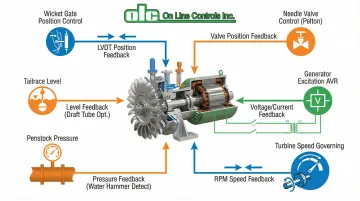
Primary control loops:
- Wicket gate position control (Francis/Kaplan turbines) - LVDTs or potentiometers provide continuous position feedback to governors
- Needle valve and deflector control (Pelton turbines) - Separate PI loops manage needle position and deflector engagement for impulse momentum control
- Generator excitation control (AVR) - PT and CT signals feed voltage and current feedback to maintain stable output
- Turbine speed governing - Tachometer signals enable real-time frequency regulation
- Penstock pressure monitoring - Analog pressure transducers detect water hammer and surge conditions
- Tailrace level control - Continuous level sensing prevents flooding and optimizes draft tube performance
These control loops work together to maintain stable power generation, but their value becomes most apparent during system disturbances.
Critical During Dynamic Events
Analog feedback is essential during rapid transients: load rejection, emergency stops, and startup/shutdown sequences. When a transmission line trips and electrical load vanishes instantly, the turbine must respond in milliseconds to prevent overspeed.
Digital systems with 50-100ms scan times introduce delays that analog loops avoid entirely. Many operators maintain analog as the primary control layer even after adding digital SCADA, because they understand analog failure modes and trust the proven reliability of systems that have operated for decades.
Key Factors Affecting Analog Feedback Performance
Signal Integrity and Electrical Noise
Turbine halls are electrically harsh environments. Large generators and switchgear produce intense electromagnetic interference (EMI) that can corrupt low-voltage analog signals.
Noise mitigation strategies:
- Standard 4-20mA current loops resist noise coupling and remain immune to voltage drops across long cable runs
- Twisted-pair shielded cables reject EMI and radio frequency interference when properly grounded
- Optical or transformer isolation prevents ground loops and protects sensitive electronics
Proper grounding is mandatory. IEEE commissioning standards require verification that cable shields are grounded correctly to prevent noise-induced errors.
Environmental Conditions
Beyond electrical noise, the physical environment poses additional challenges. Hydropower components endure temperature extremes, humidity, vibration, and oil mist in turbine halls.
Environmental specifications for industrial sensors:
- Temperature range of -25°C to +85°C for standard LVDTs
- Vibration resistance rated for 20g at 2kHz to withstand turbine resonance
- IP65 to IP68 ingress protection against water spray and dust
- Shock tolerance up to 1000g for turbine-mounted devices
Temperature-compensated sensors prevent drift as ambient conditions change. Ruggedized housings and hermetic sealing are essential for long-term accuracy.
Component Quality and Calibration
Control precision depends directly on sensor accuracy, transformer quality, and controller tuning. High-quality LVDTs achieve ±0.1% to ±0.5% accuracy—sufficient for most hydropower applications, while precision potentiometers offer similar performance when properly maintained.
Potential transformers must meet IEC 60044 or IEEE C57.13 accuracy classes to ensure reliable voltage feedback.
Calibration intervals vary by application and monitoring strategy:
- Unmonitored critical loops: Check calibration every 6 years per USBR standards
- Continuously monitored systems: Calibrate only when SCADA comparison shows drift
- Speed sensors: Verify air-gap distance and signal integrity every 3 years
- After maintenance: Recalibrate immediately after reinstalling valves or feedback linkages
Regular calibration prevents component drift from degrading control performance over time.

Common Issues and Best Practices
Troubleshooting Analog Feedback Failures
Analog systems fail in predictable patterns. Recognizing symptoms speeds up diagnosis and minimizes downtime:
Hunting/oscillation occurs when gate or speed oscillates around the setpoint:
- Cause: Incorrect PID tuning (too much gain or too little damping)
- Fix: Reduce proportional gain or increase derivative time
Sluggish response means the system responds slowly to setpoint changes:
- Cause: Mechanical binding in actuators, low signal levels, or excessive derivative damping
- Fix: Inspect linkages for friction, verify signal amplitude, and reduce derivative time
Erratic behavior shows as random jumps or noise in control output:
- Cause: Electrical noise in signal cables, failing sensors (potentiometer wear, LVDT core damage), or loose connections
- Fix: Inspect cable shielding and grounding, check sensor continuity, and tighten terminations
Modern digital governors can detect analog feedback failures automatically—for example, a 4-20mA signal dropping below 4mA triggers alarms or emergency shutdowns.
Preventive Maintenance
While troubleshooting addresses failures, structured maintenance prevents them before they impact operations:
- Inspect potentiometers for wear on resistive tracks, clean contacts, and replace if dead spots appear
- Check cables for insulation cracks, tracking, or corrosion at terminations
- Calibration verification: Compare sensor output to known references annually for critical loops
- Verify proper spacing between magnetic pickups and toothed wheels every 3 years
- Inspect cabinet air filters and vents annually to prevent overheating
Many plants maintain spare sensors and controllers to minimize downtime during failures. For applications requiring precision analog feedback, motorized potentiometers offer reliable position sensing with long service life and minimal maintenance requirements.
When to Consider Upgrades
Not every analog system needs replacement. Evaluate upgrades based on specific needs:
Consider adding digital monitoring while keeping your analog control loop when you need:
- Data logging for regulatory compliance or performance analysis
- Remote monitoring and diagnostics
- Predictive maintenance based on trend analysis
- Integration with plant-wide SCADA
Full replacement makes sense when:
- Components are obsolete with no available spare parts
- Advanced control algorithms (model predictive control, optimization) are required
- The existing system cannot meet modern grid flexibility demands
- Maintenance costs exceed replacement costs
Hybrid architectures often provide the best value: analog signals are tapped and fed into analog-to-digital converters for SCADA while the original control loop remains active.
This approach preserves proven reliability while gaining modern diagnostic capabilities.
Frequently Asked Questions
What is the main difference between analog and digital feedback in hydropower control?
Analog feedback uses continuous electrical signals with infinite resolution and no computation delay. Digital feedback samples at intervals and represents values as discrete numbers, offering better data handling but introducing sampling delays.
Why do modern hydropower plants still use analog feedback instead of fully digital systems?
Analog offers inherent speed advantages with no sampling delays and fails in predictable ways. Operators prefer analog for safety-critical control due to decades of proven reliability, while digital systems handle monitoring and analytics.
How accurate is analog feedback compared to digital sensors?
High-quality analog sensors like LVDTs and instrument transformers achieve 0.1-0.5% accuracy, sufficient for hydropower control. Digital sensors offer better resolution, but control stability depends more on proper tuning than sensor precision.
What are the most common failure modes of analog feedback systems?
Potentiometer wear creates noise or dead spots. Electrical noise coupling into cables causes erratic readings over long distances. Temperature-related component drift and cable insulation degradation require periodic inspection and recalibration.
Can analog feedback systems be retrofitted with digital monitoring?
Yes, hybrid systems are common. Analog signals are tapped using high-impedance connections and fed into converters for SCADA monitoring. The original analog control loop remains active, preserving reliability while adding diagnostics.
What maintenance is required for analog feedback devices in hydropower plants?
Periodically inspect and clean potentiometers and contacts. Verify calibration every 6 years for critical loops or when drift appears. Inspect cables for insulation damage, check magnetic pickup air-gaps every 3 years, and maintain cabinet environmental controls annually.