Introduction
Modern vessels depend on autopilot systems for the majority of their ocean voyages, with commercial ships, fishing vessels, and recreational boats worldwide relying on these systems for fuel efficiency and crew fatigue reduction. Research shows that effective autopilot use delivers fuel savings ranging from 0.5% to 4% by minimizing rudder movements and maintaining straighter courses.
Yet this efficiency hinges entirely on a component many operators overlook: the rudder feedback sensor.
Autopilot systems cannot function without accurate rudder position feedback. When sensors fail, the consequences include:
- Course deviation and increased fuel consumption
- Complete autopilot shutdown
- Unintended rudder deflections causing groundings
The NTSB investigation into the grounding of the fishing vessel Sage Catherine Lane identified a loosely mounted rudder angle sensor as a probable cause, which transmitted incorrect data and forced the autopilot to command a hard turn. The Northsea Rational incident revealed how signal connection failures between autopilot and steering gear can trigger similar deflections.
This guide explains how rudder feedback sensors work within autopilot systems, why they're essential for safe navigation, and what distinguishes reliable sensor technology in marine environments.
Key Takeaways
- Rudder feedback sensors measure rudder position and relay data to autopilot controllers
- Autopilots maintain course by comparing commanded vs. actual rudder angles
- Potentiometric sensors, resolvers, and encoders are the three primary types used in marine steering
- Faulty feedback causes course deviation or autopilot failure, directly impacting safety
- Marine-grade sensors withstand saltwater, vibration, temperature extremes, and years of continuous operation
What Are Rudder Feedback Sensors?
Rudder feedback sensors are electromechanical devices that convert the rudder's mechanical position (angular displacement) into an electrical signal. Autopilot and steering control systems process this signal to monitor rudder movement.
These sensors serve as the autopilot's eyes. While rudder angle indicators only display position to crew and steering actuators move the rudder, feedback sensors continuously verify that steering commands are being executed correctly.
USCG regulations (46 CFR 113.40-10) specify that rudder angle indicator systems must have a transmitter at the rudder head actuated by rudder movement, and this system must be independent of the steering gear control, autopilot, or dynamic positioning systems to ensure fail-safe operation.
Why Feedback Sensors Remain Critical
Even modern integrated bridge systems and dynamic positioning systems rely on accurate rudder position data as a fundamental input for navigation calculations.
Autopilot systems are essentially closed-loop control systems. Without feedback sensors confirming rudder position, the autopilot cannot verify whether steering commands are being executed correctly. This makes safe navigation impossible.
Common Sensor Types
Three main sensor technologies are used in marine applications:
- Potentiometric sensors - Resistance-based, cost-effective, proven technology
- Resolvers - Inductive sensors with no physical contact, extremely durable
- Optical/magnetic encoders - Digital output with high resolution for modern systems
Selection depends on vessel size, steering system type, and redundancy requirements mandated by classification societies.
How Rudder Feedback Sensors Enable Autopilot Navigation
Autopilot navigation operates through a continuous feedback loop where sensors, controllers, and actuators work in coordinated sequence to maintain the vessel's programmed course.
This process repeats dozens of times per second, making imperceptible corrections that keep the vessel on track despite wind, waves, and currents.
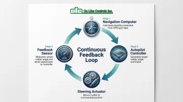
Command Signal Generation
The autopilot controller generates command signals based on navigation inputs. The navigation computer calculates required heading corrections using GPS position, gyrocompass heading, and programmed waypoints, then converts this into a target rudder angle.
Modern systems communicate using standardized protocols:
- NMEA 2000 - PGN 127245 (Rudder) transmits current angle and direction order
- NMEA 0183 - RSA sentence (Rudder Sensor Angle) provides position data
- Analog signals - 0-5V, ±10V, or 4-20mA current loops for legacy systems
Rudder Position Measurement
As the steering gear moves the rudder, the feedback sensor's shaft rotates proportionally, converting mechanical rotation into an electrical signal representing angular position.
Potentiometric sensor operation:
A wiper moves across a resistive element as the rudder rotates, creating variable voltage output that corresponds linearly to rudder angle. For example: 0V at 35° port, 5V at centerline, 10V at 35° starboard.
The sensor signal is conditioned (filtered, amplified) and transmitted to the autopilot controller where it's digitized and compared against commanded position.
The Maretron RAA100, for instance, transmits rudder PGNs at 10 times per second, providing the rapid update rate essential for responsive control.
Error Detection and Correction
The autopilot controller calculates error (difference between commanded angle and actual angle measured by the feedback sensor) typically dozens of times per second. When error exceeds the deadband threshold—usually 1-2 degrees—the controller sends adjustment commands to the steering gear.
Continuous feedback is critical because external forces constantly push vessels off course. Wind, waves, and currents require perpetual small corrections that are impossible without real-time position feedback.
If the rudder deadband is set too high (greater than 1.3 degrees), the vessel may not be controlled properly. In contrast, too-tight deadband with low-resolution sensors causes "hunting"—excessive rudder movement back and forth across the setpoint.
Stability and Performance Optimization
Modern autopilots use feedback sensor data in PID control algorithms (Proportional-Integral-Derivative) to optimize steering response.
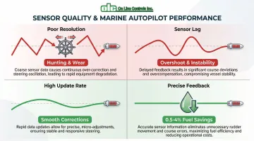
Sensor accuracy directly affects autopilot performance:
- Poor resolution causes hunting and excessive wear on steering gear
- Sensor lag causes overshoot and course instability
- High update rates enable smooth, efficient course corrections
- Precise feedback enables 0.5-4% fuel savings through minimal rudder movements and optimal course-keeping
Types of Rudder Feedback Sensors in Marine Systems
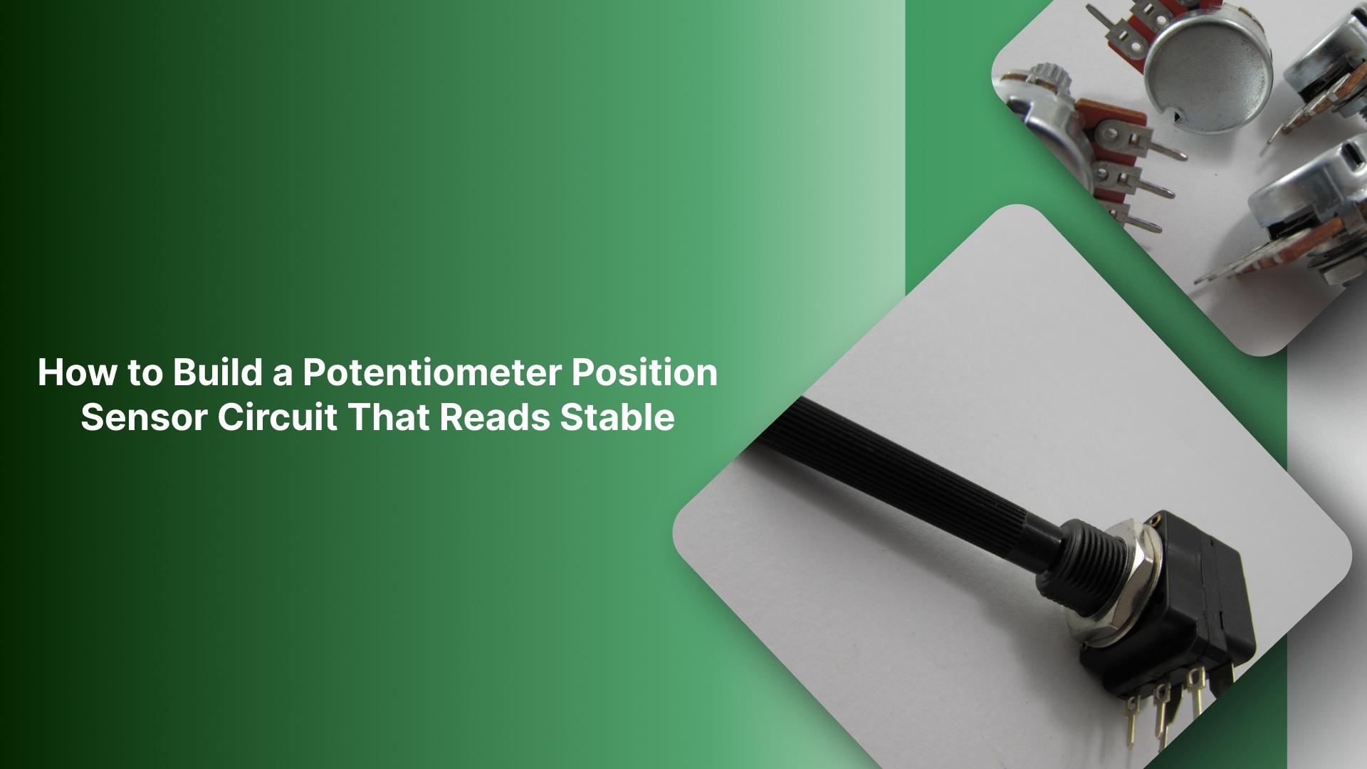
Potentiometric Sensors
Potentiometric sensors feature a resistive element with mechanical wiper, providing output voltage proportional to position. The Alphatron Rudder Feedback Unit has a maximum mechanical angle of 135 degrees; exceeding this compromises accuracy.
Advantages:
- Simple, proven technology with decades of marine service
- Cost-effective for smaller vessels and recreational craft
- Straightforward installation and calibration
Limitations:
- Mechanical wear on wiper reduces accuracy over time
- Susceptibility to vibration-induced signal noise
- Requires periodic calibration to maintain accuracy
Standard resistive senders typically follow American (240-33 ohm) or European (10-180 ohm) standards, with analog voltage outputs that integrate with most autopilot controllers.
Resolvers and Encoders
For applications requiring greater durability, resolvers use inductive sensors based on rotating transformer principles. DEIF's rudder transmitters use "no touch" magnetic angle detection technology, eliminating electromechanical wear.
Because there's no physical contact between rotor and stator, resolvers are extremely durable and preferred for large commercial vessels. These sensors offer exceptional precision, with accuracy better than ±0.25 degrees and resolution of 16 bits—enabling smooth autopilot operation without hunting.
Optical/magnetic encoders provide digital output with high resolution, often used in modern integrated bridge systems. They provide absolute position without initialization and integrate seamlessly with NMEA 2000 networks.
Environmental Protection Requirements
Marine environments demand robust protection specifications:
- IP ratings - Minimum IP56 or IP67 (the Simrad RF25N is rated IP56, while DEIF transmitters achieve IP67)
- Temperature range - Typically -25°C to +55°C operational range
- Corrosion resistance - Stainless steel housings, sealed connectors, conformal coating on electronics
- Vibration tolerance - Designed to withstand continuous engine and wave-induced vibration
Materials include aluminum alloy housings, marine-grade stainless steel shafts, and sealed bearings that prevent saltwater ingress—the primary cause of sensor failures at sea.

Safety and Reliability Considerations for Rudder Feedback Systems
Rudder feedback sensors are safety-critical components. Sensor failure can disable autopilot during ocean passages, potentially leading to course deviation, collision risk, or manual steering burden on fatigued crew.
Maritime regulations and classification societies require strict reliability standards.
Redundancy and Fail-Safe Design
IMO SOLAS Chapter II-1 and classification society rules enforce redundancy requirements. Passenger ships require 100% redundancy in main steering gear power units, while cargo ships require 50% redundancy.
DNV rules specify that rudder angle indicating systems must be arranged so that a single failure in power supply or indicating system does not cause loss of rudder angle indication on the bridge.
Modern autopilots continuously compare readings from multiple sensors and trigger alarms when discrepancies exceed tolerance thresholds.
For Dynamic Positioning vessels, DNV rules require that upon feedback failure, the rudder remains in its present position rather than moving to hard-over, which prevents unintended yaw that could compromise station-keeping.
Sensor Failure Modes and Detection
Common failure modes documented in maritime accident investigations include:
- Wiper wear in potentiometers causing signal dropout or erratic readings
- Water ingress causing short circuits and false position signals
- Mechanical binding from corrosion preventing accurate tracking
- Signal drift from temperature effects causing calibration errors
- Loose mounting hardware (identified in the Sage Catherine Lane grounding)
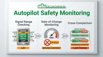
Autopilot failure detection methods:
- Signal range checking - Detecting out-of-bounds voltages that indicate sensor malfunction
- Rate-of-change monitoring - Detecting physically impossible rudder movements (e.g., 35° change in 0.1 seconds)
- Cross-comparison - Comparing redundant sensors and alarming when discrepancies exceed tolerance
Systems like the Furuno NAVpilot display specific error messages such as "RRU SETUP ERROR" or "RUDDER ANGLE ERROR" when sensor data is invalid or out of range.
Calibration and Maintenance Requirements
Sensors must be aligned with actual rudder centerline during installation. The Simrad RF25N specifies accuracy of ±0.25° within ±5 degrees of center, and ±0.5° otherwise. Periodic verification ensures accuracy hasn't drifted beyond acceptable limits.
Maintenance best practices:
- Annual calibration verification is common industry practice
- Inspection of linkages and mounting hardware every 6-12 months
- Replacement intervals of 5-10 years or based on condition monitoring
- Documentation of testing for marine insurance and port state inspections
The TSB investigation into the Salvor incident revealed that a fatigue fracture in a feedback rod occurred due to binding from misalignment. This demonstrates why proper installation and regular inspection are critical.
Regulatory Compliance and Standards
SOLAS Chapter II-1, Regulation 29 requires that main steering gear must put the rudder from 35° on one side to 35° on the other in not more than 28 seconds. The rudder angle indication system must be independent of the steering gear control system.
IMO Resolution MSC.333(90) requires that Voyage Data Recorders (VDR) record "Rudder order and response," including status and settings of the heading controller, control station, mode, and power units in use. This data proves critical in accident investigations.
Classification societies (ABS, DNV, Lloyd's) enforce type approval standards that feedback sensors must meet before installation on classed vessels.
Where Rudder Feedback Sensors Are Used in Marine Operations
Rudder feedback sensors are essential in autopilot-equipped vessels including container ships, tankers, bulk carriers, cruise ships, fishing vessels, and recreational yachts over approximately 40 feet.
The IMO High-Speed Craft (HSC) Code explicitly requires these vessels to have rudder angle indicators independent of the directional control system.
Integration with bridge systems:
Feedback sensors provide rudder position data to multiple systems simultaneously:
- Autopilot controllers for course-keeping
- Integrated navigation systems for voyage planning
- Voyage Data Recorders (VDR) for accident investigation
- Dynamic Positioning systems on specialized vessels (drill ships, cable layers)
Performance requirements by vessel type:
- High-speed vessels require faster sensor response times (20+ updates per second)
- Vessels with multiple rudders need independent feedback for each steering element
- DP vessels require sub-degree accuracy (±0.5° or better) for station-keeping
- Azimuth thruster installations need specialized feedback for both angle and thrust direction
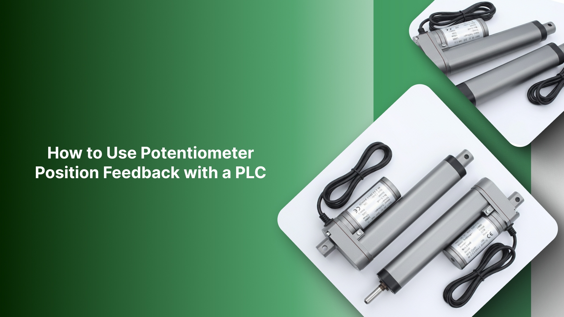
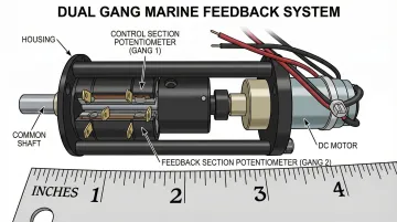
Motorized potentiometers serve as one feedback solution in marine applications. These devices provide high-precision proportional control with dual gang configurations—one potentiometer section handles control while the other supplies position feedback. This design delivers the redundancy required for safety-critical marine steering systems, with operational lifespans of 10-20 years in demanding maritime environments.
Conclusion
Rudder feedback sensors close the control loop that makes marine autopilot possible. They continuously verify that steering commands execute accurately, enabling the 0.5-4% fuel savings autopilots deliver while maintaining safe navigation through precise course-keeping.
Beyond efficiency, accurate feedback prevents dangerous situations caused by undetected steering failures. As accident investigations consistently demonstrate, sensor malfunctions contribute directly to groundings and allisions. The loosely mounted sensor on the Sage Catherine Lane and the signal connection failure on the Northsea Rational illustrate how seemingly minor sensor issues can escalate into serious casualties.
Vessel operators and marine engineers who understand feedback sensor operation can better diagnose autopilot problems, perform effective maintenance, and specify appropriate equipment for new installations or upgrades. Whether selecting potentiometric sensors for cost-effectiveness, resolvers for durability, or encoders for precision, matching sensor technology to operational requirements ensures safe, efficient navigation for years of reliable service. Whether selecting potentiometric sensors for cost-effectiveness, resolvers for durability, or encoders for precision, matching sensor technology to operational requirements ensures safe, efficient navigation for years of reliable service. Companies like On Line Controls, which manufacture precision motorized potentiometers for industrial control applications, demonstrate the broader importance of accurate feedback sensing across multiple industries where precision positioning matters.
Frequently Asked Questions
What is a rudder feedback potentiometer?
A rudder feedback potentiometer is a position sensor that converts rudder angle into a voltage signal (typically 0-10V) using a variable resistor. Autopilot systems use this signal to verify actual rudder position against commanded position.
Is a position sensor the same as a potentiometer?
Potentiometers are one type of position sensor. Marine systems also use resolvers (inductive sensors) and encoders (optical/magnetic), each using different measurement principles. Selection depends on accuracy requirements and environmental conditions.
How accurate do rudder feedback sensors need to be for safe navigation?
Commercial vessel autopilots generally require ±1-2° accuracy for effective course-keeping. The Simrad RF25N, for example, specifies ±0.25° within ±5 degrees of center. Dynamic Positioning systems demand higher precision—typically ±0.5° or better—to maintain station-keeping during critical operations like drilling or cable laying.
What happens if a rudder feedback sensor fails during ocean passage?
The autopilot disengages immediately with visual and audible alarms. The vessel must switch to manual steering, placing burden on crew. If redundant sensors are installed (required on most commercial vessels), the autopilot can continue operating with degraded redundancy. Modern systems display specific error codes like "RUDDER ANGLE ERROR" to aid troubleshooting.
How often should rudder feedback sensors be calibrated or replaced?
Annual calibration verification is common industry practice, with full recalibration performed when accuracy drifts beyond ±1-2°. Replacement intervals typically range from 5-10 years based on manufacturer recommendations and condition monitoring. Potentiometric sensors may require more frequent replacement due to wiper wear, while resolvers and encoders often last 10+ years without degradation.
Can rudder feedback sensors be retrofitted to older autopilot systems?
Yes, but compatibility must be verified carefully. Sensor type must match autopilot controller input requirements (analog voltage, resistance range, or digital protocol). Mounting provisions and electrical characteristics must be compatible with existing wiring and controllers.