
Introduction
Rudder Feedback Units (RFUs) are critical safety components installed on virtually all commercial vessels, naval ships, and large yachts. They serve as the sensory link between steering commands and actual rudder position.
Modern vessels rely on RFU accuracy within 1-2 degrees for autopilot operation, dynamic positioning, and collision avoidance. IMO and SOLAS requirements mandate this precision for redundant steering control systems.
Even though they're essential for safe navigation and fuel-efficient routing, many operators don't fully understand how these sensors work. This knowledge gap leads to delayed maintenance, improper calibration, and increased risk of steering failures. In 2011, the bulk carrier Orsula grounded after a contaminated potentiometer sent incorrect position signals, demonstrating the real-world consequences of RFU failures.
This guide explains how RFUs function in practice, what technologies power them, and why their accuracy directly impacts vessel safety, operational efficiency, and regulatory compliance.
Key Takeaways
- RFUs continuously measure and report actual rudder angle position to the ship's steering control system
- Enable closed-loop steering by comparing commanded vs. actual rudder angle for real-time corrections
- Modern RFUs use potentiometric, Hall effect, resolver, or encoder technologies, with digital systems replacing analog for improved reliability
- Mandatory under IMO regulations; critical for autopilot performance, fuel efficiency, and collision avoidance
- Systems typically feature dual or triple redundancy to meet classification society requirements
What Are Rudder Feedback Units?
RFUs are position sensors mounted on the steering gear that measure the actual angular position of the rudder and transmit this data to the steering control system, autopilot, and navigation systems.
They solve a critical operational gap: without accurate rudder position feedback, the steering system operates "open-loop" with no way to verify if steering commands are executed correctly, creating risk of course deviation, collision, and loss of control.
What RFUs Are NOT:
- Steering gear controllers — which send commands rather than measure position
- Gyrocompasses — which measure vessel heading, not rudder angle
- Rate-of-turn sensors — which measure turning speed rather than rudder position
Even with advances in integrated bridge systems and automation, RFUs remain essential. They're the only sensors that directly measure rudder position across all steering modes — manual, autopilot, joystick, and dynamic positioning.
Main RFU Types:
- Analog RFUs — potentiometer-based units common on older vessels
- Digital RFUs — Hall effect or encoder-based systems with superior reliability
- Resolver-based RFUs — high-precision units for dynamic positioning applications
The measurement principle stays consistent: mechanically couple to the rudder, convert angular position to electrical signals, and transmit data to control systems for real-time adjustments.

How Do Rudder Feedback Units Work?
RFUs operate through a continuous measurement cycle that captures rudder movement, converts it to electrical signals, and transmits position data to control systems for real-time steering adjustments.
Mechanical Coupling and Signal Initiation
The RFU sensor mechanically couples to the rudder stock or tiller arm through gearing, direct shaft connection, or linkage that rotates proportionally to rudder movement.
This coupling must be rigid and properly calibrated so the sensor accurately reflects rudder angle across the full range of motion—typically ±35° to ±45° depending on vessel design.
Proper installation requires setting the sensor's zero position to match rudder amidships, which serves as the reference point for all angle measurements.
Manufacturers recommend maintaining a 90° relationship between the tiller arm, linkage rod, and RFU arm when the rudder is centered to ensure linear feedback throughout the rotation range.
Position Sensing and Signal Generation
As the rudder rotates, the mechanically coupled sensor element moves in sync, generating an electrical output signal proportional to the angular position. The signal characteristics vary by technology:
- Analog RFUs produce voltage or resistance changes (typically 0-5V or 4-20mA current loops)
- Digital RFUs generate encoded position data or pulse trains representing absolute or incremental angle via RS-422 or CANbus protocols
Most systems use dual or triple sensors operating simultaneously to provide redundancy. If one channel fails or shows deviation beyond tolerance (typically 2-3 degrees), the system can switch to backup channels or trigger alarms, meeting SOLAS Chapter II-1, Regulation 29 requirements for independent steering control systems.
Signal Transmission and Processing
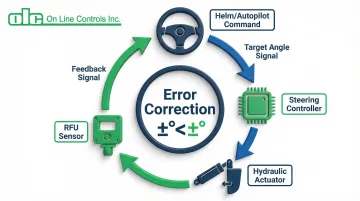
RFU signals transmit to the steering control system through shielded cables (analog) or serial communication protocols (digital). The steering controller continuously compares the commanded rudder angle—from autopilot, helm, or joystick—against the actual angle reported by the RFU.
Closed-Loop Control Principle: When the controller detects a difference between commanded and actual position, it adjusts the hydraulic or electric steering actuator to correct the error, then monitors the RFU to confirm successful correction. This feedback loop operates continuously, making hundreds of micro-adjustments per minute to maintain precise steering control.
Practical example: If the autopilot commands "Port 10°" but the RFU reports "Port 8°," the controller signals the hydraulic valves to continue moving the rudder until the RFU confirms the target angle is reached.
Error Detection and System Response
The steering system monitors RFU signals for anomalies including:
- Excessive deviation between redundant channels (typically >2° triggers investigation)
- Signal loss or wire breaks
- Values outside valid range (beyond physical rudder stops)
- Failure to respond to steering commands within expected timeframes
When the system detects RFU faults, IMO MSC.1/Circ.1398 (2011) mandates that systems trigger audible and visual alarms on the bridge, log the event, and may automatically switch to backup sensors or revert to manual steering mode.
For Dynamic Positioning Class 2 and 3 vessels, the control logic must ensure the rudder "freezes" in its current position rather than moving erratically when feedback fails.
This stage is critical: RFU failures that go undetected can result in rudder positions that don't match helm commands. The 2011 Orsula grounding occurred when contamination caused the potentiometer to send incorrect signals, showing the bridge indicator at 10° starboard while the rudder was actually unresponsive, leading the crew to misinterpret the vessel's behavior.
Types of RFU Sensor Technologies
RFUs employ different sensor technologies, each with distinct advantages in accuracy, reliability, maintenance requirements, and suitability for specific marine environments.
Potentiometric RFUs
Potentiometric RFUs use a resistive element with a sliding contact (wiper) that moves along the resistor as the rudder rotates. This creates a voltage divider whose output voltage is proportional to rudder angle.
Advantages:
- Simple design with straightforward integration
- Low initial cost
- Easy compatibility with analog steering systems from the 1970s-2000s
Maintenance Challenges:
- Mechanical wear on the wiper contact requires replacement every 5-7 years
- Contact contamination causes signal noise or dead spots
- The conductive plastic track can detach from substrate under stress
- Requires quarterly visual inspections and every-two-year electrical checks
Despite these limitations, high-quality motorized potentiometers from precision manufacturers can extend service life to 10+ years when properly maintained.
However, the maritime industry now prefers digital alternatives for new installations. Mechanical wear and contamination in potentiometric sensors have been directly linked to vessel groundings, driving the shift toward more reliable technologies.

Hall Effect and Magnetic RFUs
Hall effect RFUs use non-contact magnetic sensing where a magnet attached to the rotating shaft creates a magnetic field measured by Hall sensors. This produces a digital output signal proportional to angle without mechanical wear.
Key Advantages:
- Significantly longer service life (10-15 years typical) by eliminating sliding contacts
- "No touch" maintenance—sensing element requires virtually no upkeep
- Superior resistance to vibration, moisture, and contamination
- IP67 ratings make them ideal for harsh marine environments
Recent marine industry shifts favor Hall effect feedback systems due to their reliability benefits. These sensors are less susceptible to the failure modes that plague potentiometric designs, making them the preferred choice for heavy-duty applications and vessel upgrades.
Resolver and Encoder-Based RFUs
Resolvers use electromagnetic coupling to measure angle (common in military and high-reliability applications), while rotary encoders use optical or magnetic patterns to generate precise digital position data.
Advantages:
- Extremely high accuracy—often better than 0.1° resolution
- Absolute position output (no homing required on power-up)
- Excellent long-term stability
- Suitable for continuous 360° rotation
Typical Applications:
- Dynamic positioning systems requiring precision better than 0.25°
- Azimuth thrusters and podded propulsion
- Vessels requiring precision maneuvering where higher cost is justified by performance requirements
These high-end digital systems typically require CANbus or NMEA interfaces and are more complex to integrate than simple analog potentiometers, but their accuracy makes them essential for DP Class 2 and 3 vessels.
Where RFUs Are Used in Marine Operations
RFUs integrate with multiple vessel systems as a critical input for navigation and control functions:
Integration Points:
- Steering control system (primary interface)
- Autopilot controller (for course-keeping)
- Dynamic positioning computer (for station-keeping)
- Integrated bridge system (for navigation display)
- Voyage data recorder (for incident investigation)
These integration points require reliable feedback across all operating conditions.
Operational Environments: RFUs perform across diverse conditions—from small coastal vessels to large tankers and containerships, in conditions ranging from calm seas to heavy weather, and in temperature extremes from arctic to tropical waters.
This versatility requires robust environmental ratings (typically IP67 or higher) to withstand moisture, vibration, and temperature cycling.
Application Variations:
- Conventional rudder installations use single RFUs per rudder
- Azimuth thrusters and podded propulsion require 360-degree feedback units with specialized mounting
- Vessels with multiple rudders or steering nozzles need independent RFU systems for each control surface
- Twin-rudder vessels benefit from optimized rudder angle control, with Anschütz field tests showing fuel savings averaging just under 2%

Benefits of Accurate RFU Systems
Safety Impact
Accurate RFU feedback ensures the vessel responds predictably to helm commands, critical for collision avoidance, narrow channel navigation, and maneuvering in congested ports.
Deviations of even a few degrees can have serious consequences in restricted waters or during close-quarters situations.
Operational Efficiency
Precise rudder control enables optimal autopilot performance, reducing course deviations that waste fuel. Research using 4-degree-of-freedom simulation models indicates that accounting for drift and rudder resistance reveals fuel consumption differences of up to 2.5% compared to simpler control models.
Key efficiency benefits include:
- Minimizes "hunting" (constant small rudder corrections)
- Reduces drag from unnecessary course adjustments
- Lowers fuel consumption on long voyages
Regulatory Compliance
Classification societies and flag states require RFU systems to meet specific accuracy, redundancy, and reliability standards as part of steering gear certification.
SOLAS Chapter II-1, Regulation 29 and IMO MSC.1/Circ.1398 mandate that feedback units must be electrically and mechanically separated, with independent control systems ensuring that a single failure doesn't disable steering.
Quality RFU installation and maintenance is essential for vessel approval and insurance coverage.

Conclusion
RFUs function as the essential sensory feedback mechanism in ship steering systems. They continuously measure rudder position and enable closed-loop control that keeps commanded and actual rudder angles synchronized.
This feedback loop proves fundamental to vessel safety, fuel efficiency, and regulatory compliance.
Key takeaways for marine engineers:
- Sensor technology selection matters—traditional potentiometric designs require regular maintenance, while modern Hall effect and resolver systems offer superior reliability
- Maintenance programs must account for each technology's specific requirements and failure modes
- Quick response protocols for steering anomalies prevent incidents like the Orsula grounding caused by undetected RFU failures
Understanding these fundamentals helps operators make informed decisions that protect both vessels and crew.
Frequently Asked Questions
What causes a potentiometer-based RFU to fail?
Primary failures include mechanical wear on sliding contacts, moisture/debris contamination, corrosion in marine environments, and mechanical shock from heavy seas. Typical service life is 5-7 years, though high-quality units with proper maintenance can last 10+ years.
How do I determine the correct RFU specifications for my vessel's steering system?
Selection depends on rudder rotation range (±35° or ±45°), control system input type (analog or digital), redundancy requirements per classification society rules, and environmental factors. Consult your steering gear manufacturer and classification society requirements.
How often should RFUs be calibrated?
Calibrate during annual SOLAS-required steering gear tests, whenever steering anomalies appear, after steering gear maintenance or repairs, and when replacing RFU components.
What is the difference between analog and digital RFUs?
Analog RFUs output continuous voltage/current signals proportional to rudder angle, while digital RFUs provide encoded position data via serial communication. Digital systems offer better noise immunity, easier bridge integration, and built-in diagnostics.
Can RFUs be retrofitted on older vessels?
Yes, RFU upgrades are common during steering gear modernization, with digital Hall effect units replacing aging potentiometric systems. Retrofits require only adapter brackets and wiring updates, and can be completed during drydocking.
What are the signs of a failing RFU?
Symptoms include erratic autopilot performance, steering alarms indicating sensor mismatch, jumpy rudder angle indicators, and steering response not matching helm commands. Any of these warrant immediate inspection.