Introduction: The Hidden Variable That Makes or Breaks Multi-Lumen Extrusion
Multi-lumen medical tubing demands tolerances thinner than a human hair—often as tight as ±0.0005 inches (12.7 microns). The difference between precision production and costly scrap comes down to pressure control measured in fractions of an inch of water.
Internal air pressure directly governs lumen dimensions, wall thickness, and structural integrity—yet it's the variable most often underestimated during process optimization. Variations as small as 0.1 inches of water can cause dimensional defects in thin-walled products.
For manufacturers producing catheters, guidewire tubes, and complex multi-lumen profiles, mastering ultra-low pressure regulation is essential for maintaining tight tolerances and minimizing waste.
TLDR: Key Takeaways for Multi-Lumen Pressure Control
- Pressure variations as small as 0.1" of water cause dimensional defects in thin-walled tubing
- Each lumen requires independent pressure control to maintain dimensions and prevent collapse
- Electronic regulators respond 10–100x faster than mechanical systems — critical for bump and taper tubing profiles
- Proper pressure control reduces startup scrap by over 40% in documented implementations
- Ultra-low pressure ranges (0–30" water) require specialized regulation distinct from standard pneumatics
Why Pressure Control is the Foundation of Multi-Lumen Quality
The Physics of Pressure in Extrusion
Internal air pressure functions as a non-contact mandrel during extrusion. As molten polymer exits the die, pressurized air supports the tube structure while it cools and solidifies. This pressure counteracts external forces—cooling water, vacuum sizing, and haul-off tension—to maintain lumen shape.
The relationship is direct: increasing air pressure expands lumen inner diameter and slightly reduces wall thickness. Decreasing pressure has the inverse effect, shrinking the lumen and thickening surrounding walls. This occurs because higher pressure pushes the semi-molten polymer outward against the die geometry.
Multi-lumen tubing multiplies this sensitivity. Multiple independent channels mean thinner shared walls between lumens, and pressure fluctuations in one channel can deform adjacent lumens or the septum separating them — creating dimensional cascade effects throughout the entire profile. That physical reality has a direct cost.
The Cost of Inadequate Pressure Control
Poor pressure control directly impacts the bottom line. Real-time measurement and feedback control has reduced startup scrap by over 40% in documented medical tubing applications. Given that material costs account for 50-90% of total product cost in medical extrusion, even modest scrap reductions deliver substantial savings.
Common pressure-related defects include:
- Out-of-round lumens (ovality) from uneven cooling or unstable pressure — a common tolerance failure
- Collapsed channels when insufficient pressure lets surface tension or external vacuum win
- Wall thickness variation that compromises mechanical properties across the extruded section
- Cross-lumen deformation in multi-lumen profiles, where one unstable channel distorts shared walls and adjacent lumens
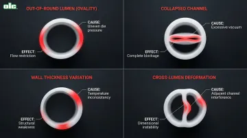
These defects compound in complex geometries. A single unstable lumen can render an entire multi-lumen profile unusable.
Why Flow Rate Variability Demands True Pressure Regulation
Flow rates shift constantly during extrusion — cuts create sudden demand spikes, spooling introduces periodic variation, and uneven puller belt pressure causes fluctuations that compound at the die.
Simple needle valves and basic regulators fail under these conditions. They control pressure only when flow stays constant; when flow changes, pressure drifts. True pressure regulation maintains setpoint independent of flow variations through force-balance designs that continuously bleed excess air, automatically compensating for demand changes on the fly.
Components of an Effective Pressure Control System
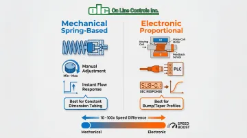
Mechanical vs. Electronic Pressure Control: Understanding Your Options
Mechanical spring-based regulators use a bleed-off valve balanced against a low-tension spring. As air pressure builds, it opens the relief valve until equilibrium is reached between air pressure and spring tension. The valve floats on a cushion of air where friction is negligible, producing hysteresis-free output even when input pressure or output flow changes dramatically.
These systems excel for constant-dimension applications. Key strengths include:
- Instantaneous response to flow changes
- Simple, reliable operation with minimal moving parts
- Smooth, oscillation-free output with proper viscostatic damping (oil-filled chambers that resist oscillation)
- Well-suited for standard medical tubing, catheter production, and steady multi-lumen profiles
Electronic proportional control systems replace the spring mechanism with a precision voice-coil linear motor. These systems accept analog voltage inputs (0-10V) from PLCs or line controllers, enabling programmable pressure profiles and high-speed switching.
Electronic control becomes necessary for:
- Bump and taper tubing requiring rapid pressure transitions
- Automated production lines with PLC integration
- Applications requiring pressure ramping synchronized with line speed changes
- Complex profiles where pressure must track dynamic process conditions
Response time differences are significant. Mechanical systems respond instantly to flow changes but adjust setpoints through manual controls or motor-driven spring adjustments. Electronic systems achieve pressure changes in less than 0.1 seconds, essential for high-speed profile switching.
Pressure Transducers: The Sensing Foundation
For multi-lumen extrusion, differential pressure measurement is critical—one side monitors internal lumen pressure while the other references the surrounding environment (often vacuum tank pressure).
Variable-capacitance transducers are the industry standard for ultra-low pressure applications. These sensors achieve accuracies of ±0.02% to ±0.11% of full scale with response times in the tens of milliseconds. Their high sensitivity and thermal stability make them ideal for medical tubing where pressure ranges often fall between 0-30 inches of water.
For medical applications requiring tolerances of ±0.0005 inches, transducer accuracy must support the dimensional precision required. Temperature-compensated designs minimize thermal drift that could cause gradual dimensional changes during production runs.
Control Valves: Precision Air Delivery
Proportional control valves modulate airflow based on controller commands. These valves use an electromagnetic coil and spring-loaded nosepiece with a precision orifice to provide continuous flow adjustment rather than simple on/off operation.
Key specifications include:
- Under 35 milliseconds response time for fast-acting proportional valves used in medical applications
- Less than 10% hysteresis of full scale for high repeatability
- Flow capacity sized to handle specific rates without creating turbulence
For constant-pressure applications, moderate response times suffice. Bump and taper tubing demands faster actuation to synchronize pressure changes with haul-off speed variations.
Mass Flowmeters: The Critical Safety Monitor
Even a precisely tuned valve system has a blind spot: lumen blockage. A pressure controller can maintain setpoint pressure with a fully blocked lumen—by simply cutting off airflow—masking a catastrophic defect until quality inspection.
Thermal mass flowmeters provide essential safety monitoring. These devices measure the mass flow rate of gas using a heated sensor element, detecting flow rates as low as a few cubic centimeters per minute. Typical specifications include flow ranges up to 20,000 SCCM with response times of approximately 20 milliseconds.
When flow drops unexpectedly while pressure remains stable, it signals a restriction or blockage requiring immediate attention.
Controllers and System Integration
Modern controllers coordinate the entire pressure regulation system. Functions include PID tuning for optimal response, setpoint management, real-time display, and communication with other line equipment.
Integration options vary by application:
- Standalone operation — manual setpoint adjustment for constant-dimension tubing
- Contact closure inputs — automated control from OD gauges that send up/down signals
- Analog voltage inputs — continuous control from PLCs for synchronized pressure profiles
- Output signals — 0-10V or 4-20mA outputs enable closed-loop feedback to master controllers
Controllers enable complete process automation, adjusting screw speed, puller speed, and internal air pressure simultaneously based on real-time dimensional feedback.
Multi-Lumen Pressure Control Best Practices
The Golden Rule: Independent Pressure Control for Each Lumen
Each lumen must have separately regulated air pressure. This fundamental requirement stems from the physics of multi-lumen extrusion—lumens have different dimensions, functions, and pressure requirements. Shared air supplies create cross-talk where pressure fluctuations in one lumen deform adjacent channels.
Independent control enables dimensional adjustments without affecting other lumens. If one lumen measures undersized, increasing its pressure expands that channel without altering the others. Multi-channel systems with dedicated regulators for each lumen — such as OLC's MultiAir units — simplify setup and ensure consistency across production runs.
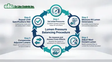
Pressure Balancing Strategies
Initial pressure settings depend on lumen size, wall thickness, and material viscosity. Use the minimum pressure necessary — excessive pressure risks over-expansion or dimensional instability.
The balancing process is iterative:
- Set initial pressures based on lumen size (smaller lumens typically require lower pressures)
- Measure all lumen dimensions after the line stabilizes
- Adjust the pressure in the lumen showing the largest deviation
- Re-measure and assess how the change affected adjacent lumens
- Compensate in other lumens if cross-effects occurred
- Repeat until all dimensions meet specifications
Maintain pressure differentials between lumens carefully. Large pressure differences across thin shared walls can cause deformation or rupture.
Coordinating Pressure with Line Speed and Temperature
Pressure requirements shift with three key process variables:
- Line speed: Faster puller speeds increase drawdown and reduce diameter. Increase air pressure proportionally to maintain wall thickness and lumen dimensions.
- Melt temperature: Hotter, lower-viscosity melts expand more readily under internal pressure. If temperature rises unexpectedly, reduce air pressure to prevent over-sizing — and increase it when the melt runs cooler.
- Process documentation: Record the relationship between line speed, temperature, and pressure for each product. This baseline accelerates setup on repeat jobs and gives you a starting point when dimensions drift.
Vacuum Sizing Integration
External vacuum tanks apply suction to the tube exterior, working with internal air pressure to control dimensions. The effective shaping force is the differential pressure—internal lumen pressure minus external tank pressure.
Vacuum levels can range from 0 to 130 inches of water, with fine control to within 0.1 inch of water critical for repeatable results. Even with precise vacuum control, each lumen still requires independent internal pressure regulation to prevent collapse.
Balance internal and external pressures carefully. Too much internal pressure overcomes the vacuum, causing over-expansion. Insufficient internal pressure allows the vacuum to collapse lumens or create ovality.
Documentation and Repeatability
Record pressure settings for each lumen as part of standard process parameters. Include:
- Pressure setpoint for each channel
- Pressure range of the regulator
- Line speed and melt temperature at those settings
- Resulting dimensional measurements
Pressure logging during production lots enables traceability and continuous improvement. When dimensional variations occur, pressure logs help identify whether control system drift or process changes caused the deviation.
Documented pressure profiles can cut setup time on repeat jobs from hours of trial-and-error to a straightforward parameter recall — especially valuable when running tight-tolerance medical or catheter tubing where every startup wastes material.
Pressure Ranges and Selection Criteria
Ultra-Low Pressure Requirements for Medical Tubing
Medical tubing operates in dramatically different pressure ranges than industrial applications. Common ranges include 0–3, 0–5, 0–15, and 0–30 inches of water—all under 1 psi. The most demanding applications use 0–2 or 0–3 inch ranges for micro-tubes and precision catheters.
These ultra-low pressures reflect the physical realities of medical tubing construction. Key drivers include:
- Thin walls and small diameters that can't withstand higher internal pressure without deforming
- Soft, flexible materials (TPU, flexible PVC) that require less pressure than stiff polymers like PEEK or Nylon
- Blowout and instability risk — even modest over-pressure causes dimensional drift or structural failure
Selecting the Right Pressure Range
Operating pressure should fall in the middle 50% of the instrument's range for optimal resolution and accuracy. A regulator with 0–30" range performs best when operating between 7.5–22.5" of water. Operating below 10% of full scale reduces accuracy and can cause reading instability.
Range selection involves a real trade-off: a wider range sacrifices resolution and makes fine adjustments harder, while a narrower range limits flexibility if process conditions change.
Select ranges based on tubing OD, wall thickness, and material. For a 0.050" OD catheter with 0.005" wall in soft Pebax, a 0–5" or 0–10" range typically works well. Larger tubing or stiffer materials may require 0–30" or higher ranges.
Pressure Measurement Units and Conversions
Pressure units vary by region and equipment manufacturer:
Key conversions:
- 1 psi = 27.68" water = 68.94 mbar
- 5 psi = 138.4" water = 350 mbar
North American equipment typically uses inches of water for ultra-low pressure applications. European and Asian manufacturers often default to mbar or kPa. Standardizing on a single unit across all measurement devices — gauges, regulators, and control interfaces — eliminates a common source of setup errors and speeds up troubleshooting when dimensions drift.
Common Pressure Control Problems and Solutions
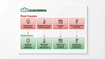
Problem 1: Dimensional Drift During Production Runs
Dimensional drift shows up as gradual changes in lumen ID or wall thickness over hours — even when the setpoint pressure reads constant.
Root causes:
- Inlet air pressure fluctuations from other plant equipment cycling on/off
- Temperature changes affecting air density and volumetric flow
- Controller drift in electronic systems
- Thermal expansion in measurement devices
Solutions:
- Install upstream pressure stabilization (dedicated air supply regulator set to 50–55 psi)
- Use differential pressure measurement referenced to ambient or tank pressure
- Implement closed-loop control with OD gauge feedback for automatic correction
- Temperature-compensate transducers to minimize thermal drift
If dimensional drift is a slow-moving problem, oscillations are the opposite — rapid and immediately visible.
Problem 2: Pressure Oscillations and Instability
Rapid pressure fluctuations appear as gauge needle movement or periodic variation in dimensional measurements.
Root causes:
- Insufficient damping in the control system
- Improper PID tuning with excessive gain
- Air supply contamination (moisture, particulates)
- Valve stiction from wear or contamination
Solutions:
- Adjust damping — add viscostatic damping or increase existing damping
- Reduce controller gain and optimize phase lead settings
- Install air filtration and moisture removal upstream
- Service or replace control valve if stiction is present
The third problem is less about the extrusion process itself and more about what happens immediately after it.
Problem 3: Lumen Collapse During Cutting or Spooling
Lumens flatten or distort during cutting or spooling — even though the cross-section held round during extrusion.
Root causes:
- Insufficient pressure to maintain structure when external support (cooling, vacuum) is removed
- Pressure drops during momentary flow interruptions
- Tubing exits the cooling section before the material fully solidifies
Solutions:
- Increase pressure setpoint slightly to provide additional structural support
- Ensure pressure control maintains setpoint during flow changes (force-balance designs maintain setpoint even during momentary flow interruptions, making them well-suited for this scenario)
- Install flow monitoring to detect restrictions or blockages early
- Extend cooling section to ensure complete solidification before handling
Advanced Applications: Bump and Taper Tubing
Why Bump/Taper Tubing Demands Dynamic Pressure Control
Medical devices often require diameter transitions along the tube length. Bump tubing features enlarged sections that enable catheter manufacturers to create access points for fiber optics, wires, or other components. Taper tubing provides gradual diameter changes for device compatibility or variable stiffness.
Creating these features requires synchronized changes in haul-off speed and internal pressure. As puller speed decreases, drawdown reduces and diameter increases naturally. Internal air pressure must ramp down simultaneously to prevent over-expansion and maintain consistent wall thickness through the transition.
The challenge: pressure must track rapid OD changes with response times under 0.1 seconds to maintain dimensional control during transitions.
Electronic Pressure Control for Profile Extrusion
Voltage-input pressure controllers accept 0-10V analog signals from line controllers, enabling synchronized pressure ramping. As the line controller adjusts puller speed to create the diameter change, it simultaneously sends a proportional voltage signal to the pressure controller.
The pressure controller responds in tens of milliseconds, adjusting internal air pressure to match the new diameter target — maintaining wall thickness consistency through transitions that might span just a few inches of tubing length.
Getting that coordination right depends on how the system is programmed. Key considerations include:
- Ramp rates that match the mechanical speed change capabilities
- Transition smoothness to avoid visible steps or ridges
- Setpoint coordination between multiple lumens in multi-lumen bump tubing
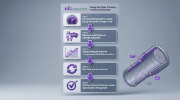
Process Development for Bump/Taper Multi-Lumen
Developing pressure profiles requires iterative refinement:
- Start with constant pressure and create the bump/taper using only speed changes
- Measure wall thickness through the transition—it will vary significantly
- Adjust the pressure curve to compensate (reduce pressure where walls are too thin, increase where too thick)
- Run another trial and measure again
- Refine the pressure profile until wall thickness remains within specification throughout the transition
Controller tuning shapes how well this process works in practice. Aggressive tuning delivers fast response but risks overshoot or oscillation; conservative tuning avoids overshoot but can lag behind speed changes, introducing dimensional errors at the transition points.
Integration with Automated Control Systems
Closed-Loop Control Architecture
Advanced extrusion lines integrate real-time dimensional measurement with automatic pressure adjustment. Laser micrometers or ultrasonic gauges measure OD, ID, or wall thickness continuously. The measurement system sends dimensional error signals to the pressure controller, which adjusts setpoints automatically to maintain target dimensions.
This architecture provides:
- Automatic compensation for process variations (material lot changes, ambient temperature shifts)
- Reduced operator intervention
- Improved consistency, particularly during startup and grade changes
In documented medical tubing applications, inline ultrasonic gauging combined with closed-loop control has reduced startup scrap by over 40%.
That level of closed-loop feedback only delivers its full value when pressure data flows beyond the line itself — into plant-level systems that track, analyze, and act on it.
Pressure Control in Industry 4.0 Extrusion Lines
Pressure controllers on modern extrusion lines connect directly to PLCs and SCADA systems via analog outputs (0-10V, 4-20mA) and digital communication protocols, feeding real-time data into plant-level infrastructure.
Benefits include:
- Real-time pressure data logging for statistical process control
- Predictive maintenance based on pressure trend analysis
- Remote monitoring and adjustment for lights-out manufacturing
- Integration with manufacturing execution systems for end-to-end lot traceability
Pressure data becomes part of the digital record for each production lot, enabling quality assurance teams to correlate dimensional variations with process conditions and pinpoint root causes when dimensions drift out of tolerance.
Frequently Asked Questions
What pressure range is needed for medical tubing extrusion?
Most medical tubing uses 0-15" or 0-30" water (0.5-1 psi), with thinner-walled products requiring lower pressures in the 0-3" to 0-5" water range. Select ranges where your operating pressure falls in the middle 50% for best accuracy.
How does air pressure affect tubing dimensions in extrusion?
Increasing internal air pressure expands lumen inner diameter and slightly reduces wall thickness. Decreasing pressure has the opposite effect—smaller ID and thicker walls. This occurs because pressure pushes the semi-molten polymer outward against the die.
What causes pressure fluctuations during tubing extrusion?
Common causes include inlet air supply variations from other plant equipment, flow rate changes from cutting or spooling operations, temperature changes affecting air density, and inadequate pressure regulation that doesn't maintain setpoint during flow variations.
How do you control pressure in multi-lumen tubing?
Each lumen requires independent pressure control with its own regulator. This allows dimensional adjustments in one lumen without affecting adjacent channels and prevents cross-talk where pressure changes deform shared walls.
What is the difference between mechanical and electronic pressure control?
Mechanical regulators use manual adjustment and are suitable for constant-pressure applications. Electronic systems accept programmable inputs, provide fast response (under 0.1 seconds), and are required for bump/taper tubing where pressure must change dynamically.
How do you prevent lumen collapse during extrusion?
Maintain sufficient internal air pressure to counteract external cooling and vacuum forces. Flow monitoring provides early warning of blockages that pressure sensors alone might miss, since a blocked lumen can maintain pressure by stopping airflow.
About On Line Controls
On Line Controls has manufactured ultra-low air pressure regulators for plastic tubing extrusion since 1980. Our MicroAir systems serve medical tubing producers worldwide — including OEM extruder manufacturers and catheter fabricators — with regulators that require no calibration and typically last 10-20 years. All products are manufactured in the USA and backed by a three-year warranty.