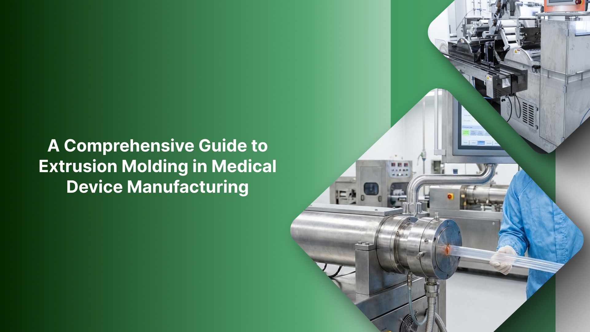
Extrusion Molding in Medical Device Manufacturing - Google Drive
In medical device manufacturing, a continuous extruded profile, whether an IV line, catheter shaft, or sheath, is only as viable as its dimensional stability. When a profile drifts even slightly in OD, wall thickness, or lumen shape, the result is immediate: excessive scrap, costly rework, and a stalled path to qualification.
This guide breaks down extrusion molding in medical device manufacturing in purely practical terms. We examine the specific control points that hold tolerance and provide a simplified IQ/OQ/PQ checklist for process validation.
If you are troubleshooting an existing line or building a new tubing program, this will help you lock in the right inputs early and solve the "same settings, different output" problem.
Key Takeaways
Medical extrusion creates high-tolerance continuous profiles for catheters, liners, and fluid-path tubing where dimensional precision is non-negotiable.
Process stability relies on the tight coordination of melt viscosity, haul-off tension, and high-resolution internal air support during the cooling phase.
Dimensional drift is rarely caused by the die alone; it is typically the result of cooling instability, mechanical ripple, or feedback lag.
Locking material and sterilization variables early in the development cycle ensures that IQ/OQ/PQ serves as proof of long-term repeatability rather than a one-time success.
What is extrusion molding in medical devices?
While often termed "extrusion molding" in project briefs, medical extrusion is a continuous forming process where heated polymer is metered through a precision die to create a profile of consistent length.
In medical manufacturing, success is measured by how stable that cross-section remains over thousands of meters, not just over a single cycle.
Core applications in medical device manufacturing
Extrusion is the primary method for producing fluid-path and access components, including:
Tubing & Liners: IV lines, peristaltic pump tubing, and ultra-thin micro-bore liners.
Catheter Shafts: Multi-lumen or jacketed shafts that require high structural integrity.
Precision Profiles: Specialized shapes that are later cut, bonded, or overmolded into finished devices.
In medical manufacturing, the differentiator isn't the die geometry; it is the standard of control. As downstream assembly, flow dynamics, and burst pressure requirements are non-negotiable, "close enough" is a failure. Precision here requires managing delicate variables, such as internal support air, to prevent the profile from deforming before it is "locked" during the cooling stage.
Extrusion vs. alternate forming methods
Extrusion is the optimal choice when you need consistent ID/OD and wall geometry across length. However, other methods are better suited for specific geometries:
Injection Molding: Best for short, discrete parts with complex 3D features like threads or bosses.
Thermoforming: The preferred route for forming flat sheets or high-volume packaging shapes.
Now that the use cases are clear, the next step is the extrusion line itself. Here’s what happens on the line and which control points decide whether your dimensions stay in spec.
How the medical extrusion line works
A medical extrusion line is simple on paper: material goes in, and a continuous tube or profile comes out. The hard part is keeping OD/ID/wall and shape stable across long runs and restarts. Most tolerance failures happen when one control point drifts quietly while everything else looks “in range.”
Step-by-step extrusion process
Feed (and drying if required): Resin/compound is loaded. For moisture-sensitive polymers, drying is a true process variable that affects melt behavior.
Melt/plasticate: The screw heats, mixes, and homogenizes the polymer into a consistent melt. This sets the baseline for viscosity stability.
Die: The melt is shaped into a tube/profile. At the die exit, the part is still hot and dimensionally unstable.
Sizing/cooling: Geometry is stabilized and “locked” as it cools. This stage often determines roundness, wall distribution, and lumen stability.
Haul-off/puller: The puller sets line speed and tension, driving draw-down and influencing OD/wall consistency.
Cut/coil: Output is cut to length or coiled without introducing deformation.
Inspect/measure: In-line gauges and/or offline checks confirm OD/ID/wall, ovality, surface condition, and lumen geometry.
The 5 control points that decide whether you stay in tolerance
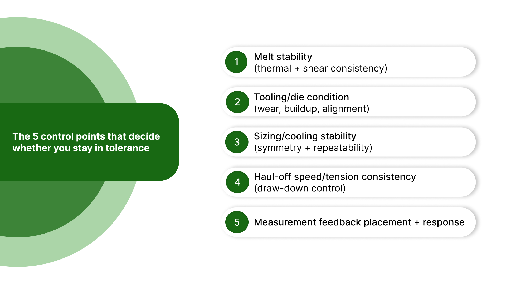
1) Melt stability (thermal + shear consistency)
Stable output needs stable viscosity. Drift in melt temperature, shear, or mixing changes how the polymer draws and freezes, which shows up as dimensional variation.
2) Tooling/die condition (wear, buildup, alignment)
Small changes in die condition can create a gradual drift that looks like a downstream problem. Wear, buildup, or misalignment can affect flow and symmetry before you see obvious visual defects.
3) Sizing/cooling stability (symmetry + repeatability)
This is where many dimensional issues are created. If cooling is uneven or sizing conditions fluctuate, you’ll see ovality, wall non-uniformity, and shape distortion even when upstream settings look steady.
4) Haul-off speed/tension consistency (draw-down control)
Speed and tension directly affect draw-down. Ripple or variation here shows up as OD oscillation, wall changes, and an inconsistent feel, especially on thin-wall parts.
5) Measurement feedback placement + response
Measurement only helps if it’s actionable. Where you measure (early vs late) and how quickly corrections take effect determines whether feedback stabilizes the process or makes it hunt.
Use this table to prioritize controls based on your extrusion type
Instead of trying to tighten everything at once, use the table below to see which risks typically show up first and which control points to prioritize for that geometry.
Extrusion type | Typical medical use | Primary risks | Controls to prioritize first |
|---|---|---|---|
Single-lumen tubing | IV/pump/drainage tubing, simple liners | OD drift, wall variation, ovality, surface marks | Sizing/cooling stability, haul-off speed/tension, melt stability, gauge placement/response |
Multi-lumen tubing | Multi-channel catheters, infusion sets | Lumen collapse, lumen imbalance, ovality, and wall non-uniformity | Support/sizing stability, cooling/sizing repeatability, measurement strategy, speed/tension stability |
Co-extrusion | Layered tubing, barrier layers, jacketed shafts | Layer thickness variation, interface instability, inconsistent feel | Melt stability (both melts), die/tooling condition, speed stability, measurement placement/response |
Multi-durometer / bump/taper | Variable stiffness shafts, transitions along length | Transition inconsistency, dimensional swings at change points | Feedback response/lag control, stable melt conditions, speed stability, repeatable changeover conditions |
Profile extrusion | Non-round profiles used in assemblies | Shape distortion, warpage, uneven shrink/cooling effects | Cooling symmetry, sizing repeatability, puller tension control, and measurement placement |
Material can be the next silent source of drift, especially once sterilization requirements come into play—even if your line settings and support conditions look stable.
Materials + sterilization: The hidden drivers of extrusion stability
In medical extrusion, material choice isn't just about the final device's performance; it dictates how the melt behaves and how sensitive the line is to drift. A line can run perfectly on one resin grade and begin "hunting" the moment the additive package or moisture condition changes.
What actually matters for extrusion stability
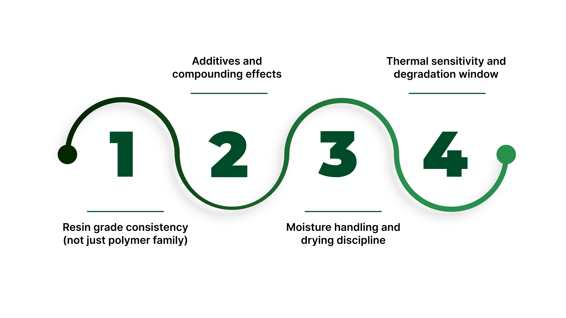
Resin grade consistency (not just polymer family)
Two materials that are both “PU” or “PE” can behave very differently if the grade, melt flow behavior, or compounding differs. Grade-to-grade variation shows up as changes in viscosity, draw-down response, and cooling shrink, so OD and wall thickness can shift even if setpoints don’t.
Additives and compounding effects
Plasticizers, colorants, fillers, processing aids, and lubricants can alter flow, surface finish, and how the material freezes. In medical work, these changes also affect what needs to be verified (surface, clarity, extractables-related testing handled by your compliance team, etc.), so “small” additive changes often aren’t small operationally.
Moisture handling and drying discipline
For moisture-sensitive resins, moisture shows up as inconsistent melt behavior, bubbles/voids, surface issues, and variability in draw-down. Drying parameters (time, temperature, dew point) become part of the process window, not a pre-step you can improvise.
Thermal sensitivity and degradation window
Some materials are less forgiving if barrel temperatures, residence time, or shear creep upward. That instability can look like random drift until you correlate it with thermal history (start-ups, slowdowns, long holds, or screw recovery changes).
Sterilization compatibility is a stability constraint, not a checkbox
The sterilization method often narrows the material options and alters what constitutes “acceptable” output after processing and aging.
Material Tolerance: Certain polymers yellow or become brittle under Gamma or E-beam; others may lose dimensional integrity during high-heat Autoclave cycles.
Validation Scope: Post-sterilization performance checks must be tied back to the extrusion dimensions. If sterilization causes the material to shrink or swell, your "in-spec" window during extrusion must account for that shift.
Lock these inputs early (so you don’t chase drift later)
Treat these as “must-define” before you run trials, request quotes, or write validation plans:
Exact resin grade/compound ID (not just polymer name)
Allowed substitutions (what is acceptable, what is not)
Additive limits (colorant %, plasticizer/filler constraints, processing aids)
Drying method + parameters (temperature, time, dew point target where applicable)
Sterilization method (and any post-sterilization performance checks tied to the part)
Change-control triggers that often force re-qualification
These material changes are most likely to move dimensions or invalidate prior evidence:
If you change resin grade/supplier/compound, expect re-testing because viscosity + shrink can shift OD/wall.
If you change additives (colourant/plasticiser/filler %), expect surface + stability changes.
If you change drying method/parameters, expect melt behaviour drift on moisture-sensitive resins.
If you change the sterilization method or acceptance criteria, expect re-qualification because post-sterilization properties can move.
With material inputs locked, we can now address the core pain: how to keep OD/ID/wall stable and avoid the failure modes medical extrusion teams fight most.
How to control OD/ID/wall and prevent ovality, lumen collapse, and drift
Medical extrusion quality is mostly dimensional control. If OD, ID, wall, or lumen geometry moves, everything downstream gets harder assembly fit, flow performance, burst targets, and qualification evidence. The goal isn’t “perfect setpoints.” It’s a stable process that holds geometry over time.
What you’re controlling
OD and ID: The baseline specs that trigger most scrap.
Wall thickness (average + uniformity): Critical in thin-wall tubing where non-uniformity creates weak points.
Ovality/roundness: Usually a result of thermal shock or insufficient internal support in the cooling tank.
Lumen shape and balance (multi-lumen): In multi-lumen profiles, preventing channel-to-channel variation and collapse is the highest hurdle.
Surface finish: Marks, chatter, or surface defects that can signal instability upstream.
The levers that stabilize dimensions
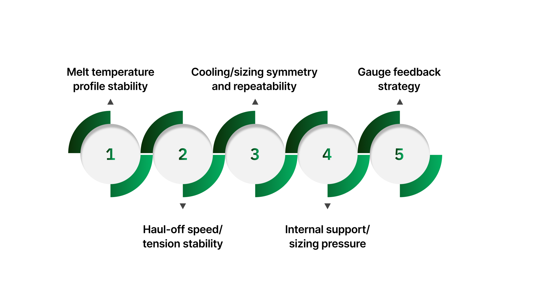
Melt temperature profile stability
Controls viscosity consistency and how the material responds to draw-down and cooling. If the melt behaves differently run-to-run, dimensions will follow.
Quick check: Compare actual barrel zone behavior and melt consistency during steady-state vs after slowdowns/restarts.
Haul-off speed/tension stability
Controls drawdown directly. Even a small speed ripple can show up as OD oscillation or wall variation, especially on thin-wall tubing.
Quick check: Look for repeating dimensional patterns that match puller speed, ripple, or tension changes.
Cooling/sizing symmetry and repeatability
Often, this is the biggest determinant of roundness and wall uniformity. If the part freezes unevenly, it becomes oval, or the wall shifts, even if the melt and speed are steady.
Quick check: Confirm cooling/sizing conditions are consistent across the circumference and stable over time (not “good at start, worse after an hour”).
Internal support/sizing pressure
Supports geometry while the polymer is still soft. This can be the difference between stable lumens and intermittent collapse, or between round and slightly flattened tubing.
Quick check: Watch whether shape defects worsen on thin-wall sections, transitions, or long runs where subtle drift accumulates.
Gauge feedback strategy
A gauge isn’t in control unless it drives a reliable correction. Placement too far downstream creates lag; noisy signals create chasing.
Quick check: Confirm the measurement is taken close enough to the point where geometry is stabilized, and that corrections change the process smoothly rather than overshooting.
Defect → likely cause → lever → quick check
Defect/symptom | Likely cause | Lever to tighten first | Quick check |
|---|---|---|---|
OD oscillation (up-down pattern) | Puller speed ripple and/or unstable sizing/cooling conditions | Haul-off stability first, then sizing/cooling repeatability | Does the oscillation frequency match the puller ripple behavior or a periodic cooling variation? |
Ovality (not round) | Asymmetric cooling/sizing or insufficient geometry support while the tube is still soft | Cooling/sizing symmetry first, then support conditions | Does ovality worsen at higher speed, thinner walls, or warmer conditions? |
Lumen collapse/lumen imbalance (multi-lumen) | Inadequate or inconsistent support/sizing conditions plus channel-to-channel imbalance | Support/sizing stability + channel balance first, then measurement strategy | Does collapse correlate with long runs, transitions, or the same lumen(s) failing first? |
Once you’ve defined the controls that hold dimensions steady, the last step is to prove repeatability with evidence so that quality teams can defend the process during validation and change control.
Validation + verification: Ensuring repeatable performance
In medical extrusion, validation prevents the "trial-run trap," where a process runs perfectly for an hour during testing but fails during a full production shift. The goal is to prove that the process is capable of repeatedly hitting specifications under real-world conditions.
IQ/OQ/PQ: The extrusion framework
1. IQ (Installation Qualification): “Is the equipment capable?”
Hardware Confirmation: Verify that the extruder, cooling systems, puller, and gauges are installed per manufacturer specs.
Calibration: Ensure all sensors, especially temperature controllers and measurement tools, are calibrated and NIST-traceable.
Utility Stability: Confirm that shop air and power are stable; fluctuations here are a common root cause of "unexplained" drift.
2. OQ (Operational Qualification): “What is our process window?”
Variable Identification: Define the limits for melt temperature, haul-off speed, and internal support pressure.
Challenge Trials: Run at "worst-case" conditions (high/low speed, high/low temp) to find where the process begins to drift.
Alarm Limits: Record the point where dimensions fall out of spec and set your equipment alarms accordingly.
3. PQ (Performance Qualification): “Can we sustain it?”
Shift Consistency: Run multiple lots using different operators and shift patterns to ensure reproducibility.
Start/Stop Performance: Validate that the process stabilizes quickly after a restart without excessive scrap.
Long-Term Capability: Prove that results (OD/ID, wall, ovality) remain within statistical limits across the entire run.
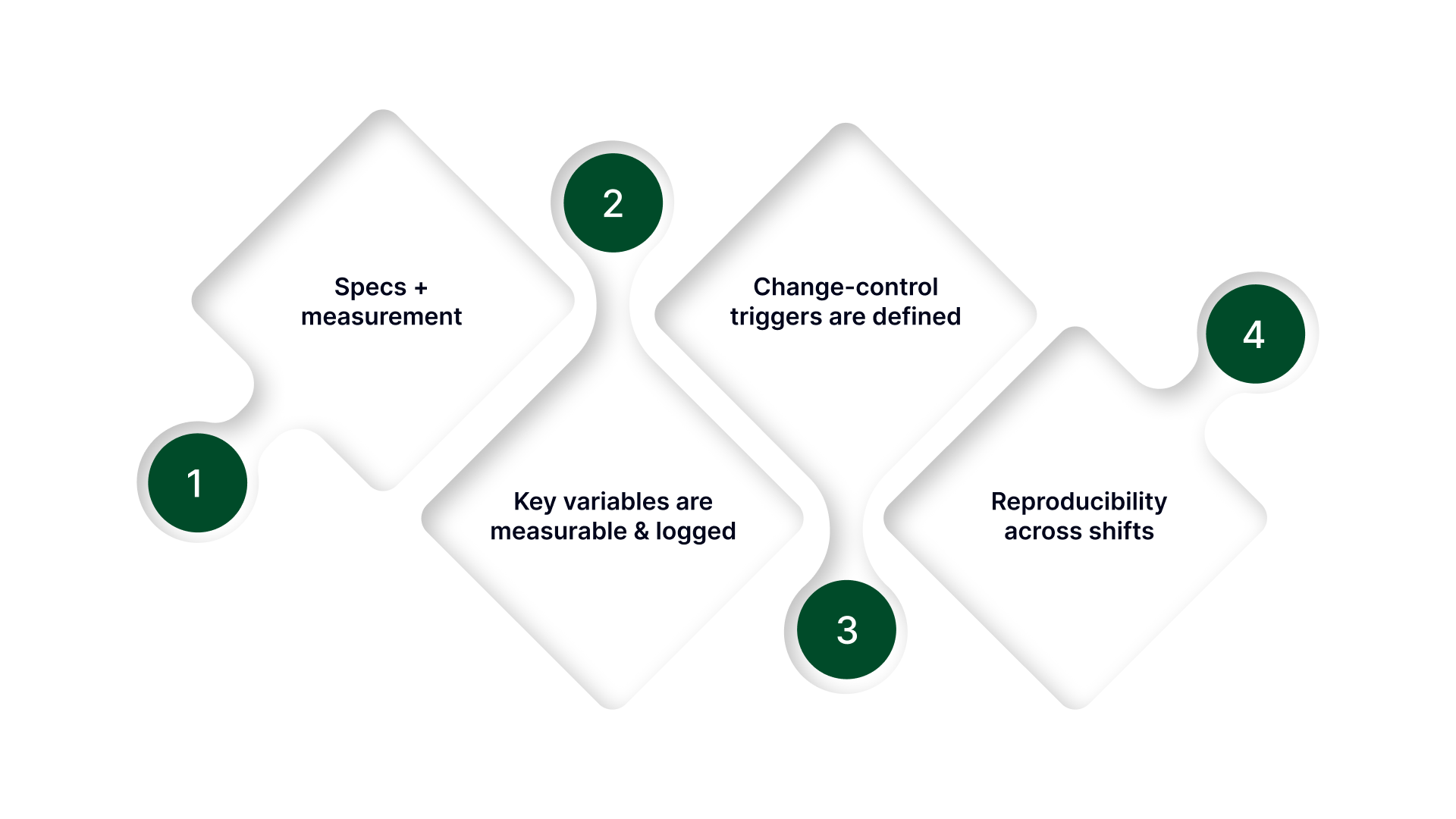
The pre-validation verification checklist
Use this checklist before starting trials or requesting a quote. If an item is vague, it will lead to "re-work" during validation.
Specs + measurement
OD/ID/wall targets + tolerance (and any ovality/lumen criteria) are clearly defined.
The measurement method is defined (in-line vs. offline, tool type, and sampling plan).
Gauge placement is intentional (close enough to be actionable, not so late that it adds lag).
Key variables are measurable and logged
The melt temperature profile is monitored (setpoints and actuals).
Haul-off speed/tension is measurable and stable.
Sizing/cooling conditions are controllable and repeatable.
If using internal support/sizing, the method and conditions are stable and monitorable.
Feedback corrections are defined (manual vs automated, correction step sizes, response expectations).
Change-control triggers are defined
What forces review/re-qualification:
material grade/supplier/compound change
tooling/die changes or refurbishment
measurement method or gauge placement changes
process window changes beyond approved ranges
Reproducibility across shifts
The same setup can be repeated by different operators.
Start-up and restart conditions are documented (what gets reset, what gets checked first).
Evidence exists that output stays in tolerance across time, not just at the start of a run.
When your mechanical setup and material inputs are locked, yet you still face intermittent ovality or lumen collapse, the root cause is almost always an invisible lack of stability in your internal air support.
How On Line Controls stabilize your extrusion process
In medical-grade extrusion, the difference between a round tube and a rejected lot is often a fraction of an inch of water column pressure. Most "standard" industrial regulators lack the resolution to manage these ultra-low ranges, leading to a process that "breathes" or hunts during cooling.
On Line Controls (OLC) fills this precision gap, providing the specialized air stability necessary to maintain the internal geometry of your most complex profiles:
Match you to the right ultra-low pressure range so small pressure changes don’t swing OD or shape.
Maintain stable internal support/sizing pressure when geometry support is the limiter (thin-wall tubing, profiles, multi-lumen work).
Enable signal-driven pressure setpoints when you need controlled changes (taper/bump behavior) without manual chasing.
Provide multi-channel support so each lumen can be stabilized independently when required.
Why teams trust this approach
On Line Controls design for the realities of the production floor, not just the laboratory. By combining in-house testing with custom pressure ranges, from ultra-low water columns to higher PSI, we ensure your line has the exact sensitivity it needs. Every unit is backed by a rugged warranty and a direct troubleshooting pathway, providing a "set it and forget it" reliability that minimizes downtime in 24/7 manufacturing environments.
Want a quick spec check? Send the inputs below, and we’ll confirm the right approach and pressure range:
Part type (single/multi-lumen/profile) + lumen count
ID/OD/wall targets + tolerance + ovality limit
Material + additives + drying notes + sterilization method
Line speed range + gauge type + gauge placement
Current sizing/support method + expected pressure range (if known)
Failure pattern (drift/ovality/collapse/slow response)
Conclusion
Medical extrusion looks simple until you’re the one trying to hold OD/ID/wall and lumen geometry across long runs, restarts, and shift changes.
The fastest way to get stable output is to stop treating issues as “die problems” by default and focus on the control points that actually drive variation: melt stability, sizing/cooling repeatability, haul-off speed/tension, and measurement feedback that’s close enough to act on.
Lock material and sterilization constraints early, define what changes trigger re-testing, and use the validation checklist to make your process defensible, not just “working today.” When those inputs are clear and measurable, IQ/OQ/PQ becomes a way to prove repeatability instead of a paperwork exercise.
If you’re near tolerance limits or seeing drift, start by tightening the stability of the conditions that support geometry during cooling. Small improvements there often remove most of the variation before you change tooling, re-run trials, or expand validation scope.
FAQs
What is the purpose of extrusion molding in medical device manufacturing?
Extrusion molding is used to produce continuous, high-tolerance profiles like tubing, catheter shafts, sheaths, and liners. The purpose is consistent geometry over long lengths, so downstream assembly, flow performance, and qualification results stay predictable.
What are the key advantages of extrusion molding for medical devices?
It delivers tight ID/OD/wall control over long runs, supports complex cross-sections (single- and multi-lumen), and scales well for high-volume continuous production. It also enables co-extrusion and multi-durometer designs when you need layers or stiffness transitions.
How is extrusion molding different from injection molding?
Extrusion is a continuous process that creates long, constant cross-sections (tubing/profiles). Injection molding creates discrete 3D parts by filling a closed mold cavity (features like bosses, threads, complex shapes). If you need “length + consistent cross-section,” extrusion fits. If you need “3D geometry per part,” injection fits.
When should you choose extrusion molding instead of injection molding?
Choose extrusion when performance depends on a consistent cross-section over length (ID/OD/wall, lumen geometry, surface). Choose injection when the part is short and feature-rich, or when geometry changes across the part and can’t be made as a continuous profile.
What are common medical components made with extrusion molding?
IV and pump tubing, catheter shafts, sheaths, liners, multi-lumen tubing, co-extruded barrier layers, and small precision profiles that get cut, bonded, or overmolded into finished devices.